
21 kV Grid Service for a Geothermal Drilling Rig
Calpine | The Geysers Geothermal Field – Drilling Rig Power Study | The Geysers, California
Project Overview
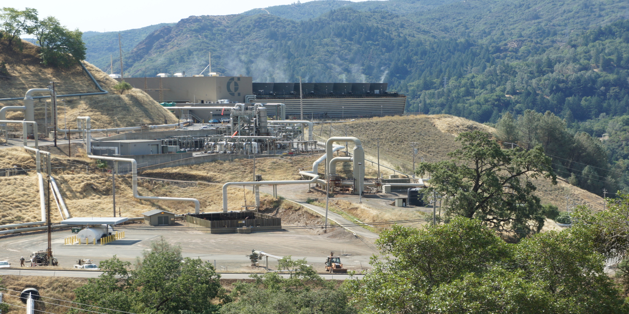
Calpine’s drilling rig at The Geysers was powered by four rented Kato diesel generator sets, each rated 2,000 kVA (1,400 kW) at 600 V, three-phase, running in automatic paralleling. As diesel fuel costs climbed, Calpine looked at serving the rig from the adjacent 21 kV overhead distribution system instead. EETS was engaged to study that switch and recommend how to make it work.
The catch was the load itself. A drilling rig of this kind is dominated by 6-pulse rectifier drives, which draw heavily distorted current rich in 5th- and 7th-order harmonics. Those harmonics cause extra heating and losses in the iron cores of transformers and machines, so the central engineering question was not simply whether the 21 kV system could carry the load, but how to serve it through a new transformer without the harmonics cooking that transformer.
EETS analyzed the harmonic loading, confirmed the 21 kV system could accommodate the addition, compared three ways to handle the harmonic heating, and recommended a harmonic-rated (K-factor) transformer as the most cost-effective, robust solution.
From Rented Diesels to Grid Power
The proposed configuration serves the rig from the 21 kV overhead distribution system through a new 4 MVA, 21 kV : 600 V transformer with 21 kV primary protection. The transformer secondary feeds the rig through a manual transfer switch, configured as an open-transition (dead) transfer with no paralleling between the diesel generators and the 21 kV system, so the two sources are never tied together. The rig sits roughly three miles down the line from the 21 kV regulating bank, which uses a load-tap-changing (LTC) transformer.
On the capacity side, the picture was favorable: the 21 kV system was lightly loaded, and the new 4 MVA transformer load – about 110 A at 21 kV – could be accommodated, with setting changes to the load-drop-compensator controls at the LTC likely needed to provide voltage support for the new load’s characteristics. Because the new transformer’s impedance, its delta-connected primary, and the relative stiffness of the 21 kV system all work to attenuate harmonics upstream, the harmonics would not significantly distort the 21 kV system voltage. The consequence of that, however, is that the harmonic burden lands squarely on the new transformer.
Project Challenge
Harmonics That Heat the Transformer, Not the Grid
A standard 4 MVA transformer serving this rig would run hot. The 6-pulse rectifier load’s distorted current waveform drives additional eddy-current and stray losses in the transformer core and windings, and because the stiff 21 kV system and the transformer’s own impedance keep the distortion from propagating upstream, the transformer absorbs the harmonic heating rather than passing it on. Sizing the transformer on MVA alone would understate the real thermal duty; the design had to account for how much harmonic content the transformer would actually have to tolerate.
A Solution That Pencils Out
Several textbook fixes for harmonics were poor fits here. Active and passive 5th- and 7th-harmonic filters were set aside as prohibitively expensive given the load’s large ampacity and high harmonic content. Any acceptable answer had to tolerate the harmonics reliably, avoid introducing new voltage-regulation problems on a line already three miles from its regulator, and do so at a cost that made grid service worthwhile against the diesel fuel it was meant to replace. The study had to weigh the realistic options against one another, not just name one.
Client
Calpine Corporation (The Geysers)
Sector
Power Generation / Geothermal
Location
The Geysers geothermal field, California (Sonoma / Lake County)
Services
Power System Study │ Harmonic Loading Analysis │ Transformer Specification │ Options and Cost Analysis │ Distribution Engineering

Drink
As part of this expansion, AWA identified an opportunity to recover energy that was previously being wasted.
Client
Calpine Corporation (The Geysers)
Sector
Power Generation / Geothermal
Location
The Geysers geothermal field, California (Sonoma / Lake County)
Services
Power System Study │ Harmonic Loading Analysis │ Transformer Specification │ Options and Cost Analysis │ Distribution Engineering
Drink
As part of this expansion, AWA identified an opportunity to recover energy that was previously being wasted.
Project Overview
Calpine’s drilling rig at The Geysers was powered by four rented Kato diesel generator sets, each rated 2,000 kVA (1,400 kW) at 600 V, three-phase, running in automatic paralleling. As diesel fuel costs climbed, Calpine looked at serving the rig from the adjacent 21 kV overhead distribution system instead. EETS was engaged to study that switch and recommend how to make it work.
The catch was the load itself. A drilling rig of this kind is dominated by 6-pulse rectifier drives, which draw heavily distorted current rich in 5th- and 7th-order harmonics. Those harmonics cause extra heating and losses in the iron cores of transformers and machines, so the central engineering question was not simply whether the 21 kV system could carry the load, but how to serve it through a new transformer without the harmonics cooking that transformer.
EETS analyzed the harmonic loading, confirmed the 21 kV system could accommodate the addition, compared three ways to handle the harmonic heating, and recommended a harmonic-rated (K-factor) transformer as the most cost-effective, robust solution.
From Rented Diesels to Grid Power
The proposed configuration serves the rig from the 21 kV overhead distribution system through a new 4 MVA, 21 kV : 600 V transformer with 21 kV primary protection. The transformer secondary feeds the rig through a manual transfer switch, configured as an open-transition (dead) transfer with no paralleling between the diesel generators and the 21 kV system, so the two sources are never tied together. The rig sits roughly three miles down the line from the 21 kV regulating bank, which uses a load-tap-changing (LTC) transformer.
On the capacity side, the picture was favorable: the 21 kV system was lightly loaded, and the new 4 MVA transformer load – about 110 A at 21 kV – could be accommodated, with setting changes to the load-drop-compensator controls at the LTC likely needed to provide voltage support for the new load’s characteristics. Because the new transformer’s impedance, its delta-connected primary, and the relative stiffness of the 21 kV system all work to attenuate harmonics upstream, the harmonics would not significantly distort the 21 kV system voltage. The consequence of that, however, is that the harmonic burden lands squarely on the new transformer.
Project Challenge
Harmonics That Heat the Transformer, Not the Grid
A standard 4 MVA transformer serving this rig would run hot. The 6-pulse rectifier load’s distorted current waveform drives additional eddy-current and stray losses in the transformer core and windings, and because the stiff 21 kV system and the transformer’s own impedance keep the distortion from propagating upstream, the transformer absorbs the harmonic heating rather than passing it on. Sizing the transformer on MVA alone would understate the real thermal duty; the design had to account for how much harmonic content the transformer would actually have to tolerate.
A Solution That Pencils Out
Several textbook fixes for harmonics were poor fits here. Active and passive 5th- and 7th-harmonic filters were set aside as prohibitively expensive given the load’s large ampacity and high harmonic content. Any acceptable answer had to tolerate the harmonics reliably, avoid introducing new voltage-regulation problems on a line already three miles from its regulator, and do so at a cost that made grid service worthwhile against the diesel fuel it was meant to replace. The study had to weigh the realistic options against one another, not just name one.
Engineering Solution
Quantifying the Harmonic Duty with a K-Factor Analysis
EETS characterized the rig load and computed the transformer’s required harmonic rating. The total load is about 2.394 MVA: a 6-pulse rectifier load of 2.286 MVA (2,200 A at 600 V), general motor and non-motor load of 0.676 MVA, and two 75 HP motors totaling 0.160 MVA. Weighting each portion by its harmonic loss factor – the rectifier load at a K-13 level and the remaining load at a K-4 level – produced a combined harmonic demand of 153.6. A 4 MVA transformer rated only K-4 provides a capability of 103.3, short of the demand, while a 4 MVA K-13 transformer provides 231.0, comfortably above it. The analysis therefore established that a 4 MVA transformer must be K-13 rated to serve this load.
Weighing Three Ways to Handle the Heat
EETS compared three approaches. Current-limiting reactors of roughly 5% impedance on the transformer output would isolate the transformer from the harmonic currents, but at the required 2,200 A, 600 V rating they would be large air-insulated coils needing an enclosure, and their added impedance would introduce voltage-regulation issues. Oversizing the transformer and adding fan cooling was the second path, but a fan-cooled 4 MVA unit was judged insufficient for the harmonic heating; a 5 MVA base rating with fans and secondary bushings up to 6,000 A would be needed. The third path, a K-factor transformer, adds core steel to tolerate the harmonics without upsizing the windings and bushings that oversizing entails.
The Recommendation and Its Integration
EETS recommended the 4 MVA, OA, 65 °C, 21 kV : 600 V, K-13 transformer as the best solution. It tolerates the harmonics without relying on mechanical cooling to reject the extra heat, and it does so at a lower cost than the oversized fan-cooled alternative while avoiding the bulk and voltage-regulation side effects of the output reactors. Around that transformer, the design keeps 21 kV primary protection, the open-transition manual transfer switch that prevents any paralleling with the diesel gensets, and the load-drop-compensator setting adjustments at the LTC needed to hold voltage for the new load three miles down the line.
Key Technical Elements
Parameter | Detail |
Existing Power | Four rented Kato diesel generator sets, 2,000 kVA (1,400 kW) each at 600 V, three-phase, auto-paralleled |
Rig Load | ≈ 2.394 MVA total – 6-pulse rectifier 2.286 MVA (2,200 A @ 600 V), general load 0.676 MVA, two 75 HP motors 0.160 MVA |
Harmonic Content | 6-pulse rectifier drives producing strong 5th- and 7th-order harmonic currents |
New Source | Adjacent 21 kV overhead distribution (lightly loaded); 4 MVA load ≈ 110 A at 21 kV |
New Transformer | 4 MVA OA, 65 °C, 21 kV (delta) : 346/600 V (wye), oil-filled padmount/substation, assumed 6% impedance |
Transfer | Open-transition (dead) manual transfer switch – no paralleling between the diesel gensets and the 21 kV system |
Voltage Support | Load-drop-compensator setting changes at the LTC regulating bank, roughly three miles up the line |
K-Factor Requirement | Weighted harmonic demand 153.6 – 4 MVA K-13 (capability 231.0) required; K-4 (103.3) insufficient |
Options Considered | Output reactors; oversize to 5 MVA + fans; K-13 transformer |
Recommendation | 4 MVA OA 65 °C, 21 kV : 600 V, K-13 transformer – harmonic-tolerant without fans, most cost-effective |
Project Outcome
EETS gave Calpine a clear, costed path off rented diesel generation. The study confirmed that the lightly loaded 21 kV system could carry the rig, quantified the harmonic duty the new transformer would face, and recommended a 4 MVA, K-13 transformer sized by that analysis – chosen over harmonic-isolation reactors and an oversized, fan-cooled transformer as the most cost-effective and robust answer. The recommended scheme serves the rig through 21 kV primary protection and an open-transition transfer switch that never parallels the grid with the diesels, with load-drop-compensator adjustments at the LTC to support voltage on a line whose regulator sits three miles away. With the harmonic loading analysis and the option-by-option cost comparison in hand, Calpine had both the recommendation and the reasoning behind it to move from rental diesels to grid power.
Value Delivered by EETS
EETS reframed a fuel-cost decision as the harmonics problem it really was, quantified it, and recommended the option that handled it most economically.
Naming the Real Problem - and Measuring It
The easy version of this project is “put a transformer on the 21 kV line.” EETS identified that the governing issue was harmonic heating in that transformer, driven by the rig’s 6-pulse rectifier load, and that because the stiff grid and the transformer impedance keep the distortion from spreading upstream, the transformer itself carries the burden. Rather than guess at a safety margin, EETS ran a K-factor analysis that turned the load’s harmonic content into a specific requirement – K-13 – and showed exactly why a K-4 transformer of the same MVA would fall short.
Options Weighed on Cost and Consequence
EETS did not simply propose a fix; it compared three, on price and on side effects. Output reactors were cheap but bulky and would degrade voltage regulation; an oversized fan-cooled transformer would work but cost far more and lean on mechanical cooling; the K-factor transformer tolerated the harmonics in the core itself, without fans, at the lowest cost of the workable options. Laying the alternatives side by side let Calpine see not just what was recommended, but what was traded away by the choices that were not.
A Grid-Integration Plan, Not Just a Transformer
The recommendation came with the pieces needed to connect it safely to the existing system: 21 kV primary protection, an open-transition transfer switch so the utility source and the diesel gensets are never paralleled, and load-drop-compensator settings at the LTC to hold voltage for a new load three miles from its regulator. That turned a fuel-saving idea into an engineered service Calpine could actually build against the distribution system it already had.
Drink
As part of this expansion, AWA identified an opportunity to recover energy that was previously being wasted.