
4 MGD Membrane Microfiltration Plant Expansion
Thermalito Water District (TID) | Water Treatment Plant 4 MGD Expansion | Thermalito, California
Project Overview
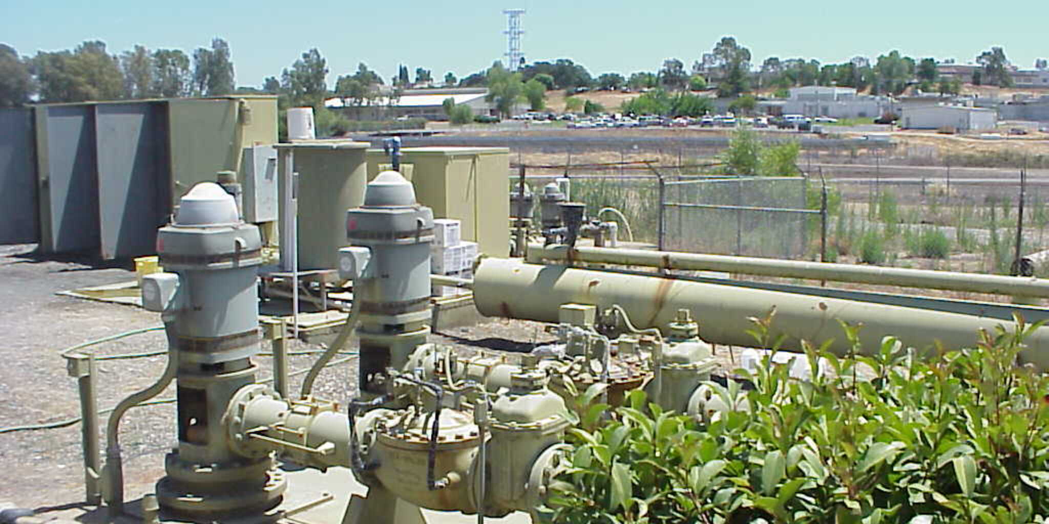
The existing Thermalito water treatment plant comprises a raw water pump station, a 6 MGD pressure filter system, a treatment building, hypochlorite tanks, a 1 MGD clearwell, and two unlined settling ponds. Two banks of three pressure filters each, rated 3 MGD per bank, are in service, and produce roughly 170,000 gallons per day of backwash wastewater at full capacity. The pressure filters rely on alum (aluminum sulfate) as a coagulant, and their backwash discharges to the unlined settling ponds, where the supernatant is settled through a first and second pond and then recycled back to the raw water intake.
The District engaged EETS to design an expansion of the plant built around membrane microfiltration. The design covers a 4 MGD microfiltration plant capable of delivering up to 4.8 MGD for sustained periods, its connection to the existing pressure filter plant, and all of the associated controls, power, and instrumentation – including the interface to the existing filter controls. The microfiltration expansion is one step in a phased path toward an ultimate 20 MGD plant.
Once the microfiltration plant is operational, the design keeps one of the two existing pressure filter banks in standby and reserves the other for emergency use only. When demand exceeds the microfiltration plant’s capacity but remains below 6 MGD, the District draws on its supply wells to meet demand until demand exceeds 6 MGD. EETS evaluated multiple treatment approaches for the expansion – retaining pressure filtration, gravity filtration, and microfiltration – and the membrane microfiltration process was selected.
The 4 MGD Microfiltration Expansion
The new plant is built on Pall membrane microfiltration. The raw water pump delivers water through the microfilter modules directly to the clearwell, the same flow path the existing pressure filters use, with a 125 HP raw water pump serving the microfiltration process. The membrane valve skids and module skids connect to a PLC furnished by the membrane supplier, and the process is supported by two reverse-filtration pumps and two compressors. For the 4 MGD stage these are 10 HP units, sized to be replaced by larger pumps and compressors as the plant is expanded toward its ultimate 20 MGD capacity.
Choosing microfiltration set the shape of the rest of the design. Because membrane filtration screens particulates without an alum coagulant, the expansion removes the source of the aluminum that had been accumulating in the plant’s sludge and soil, while the existing pressure filters are retained only as standby and emergency capacity rather than run day to day.
Project Challenge
An Environmental Problem the Existing Process Could Not Solve
The alum used in the existing pressure filters had a consequence beyond treatment: the aluminum concentration in the plant’s sludge area had increased by over 465%. Because the backwash from the alum-based filters discharges to unlined settling ponds, that aluminum was loading into the soil. No amount of tuning the existing filters would reverse it — the coagulant itself was the source. The expansion had to introduce a treatment process that could bring the aluminum concentration in the sludge back down to the level of virgin soil, which meant moving away from alum-based filtration altogether.
Making a New Plant Work Within a Live, Multi-Source System
The microfiltration plant would not run alone. It had to operate in concert with the existing pressure filter banks and the District’s supply wells to hold target levels in both the clearwell and the finished water storage tank, and to keep the existing filters available as standby and emergency capacity. Coordinating three different sources of supply – each with its own start and stop behavior – around shared tank and clearwell levels, without cycling pumps or losing the target elevation, was as much a controls problem as a process one, and it had to be designed to extend cleanly as the plant grew toward 20 MGD.
Client
Thermalito Water District (referred to as “TID” in the project documents) |
Sector
Public / Municipal Water Utility |
Location
Process Engineering │ Electrical Design │ Controls and Instrumentation │ PLC / HMI / SCADA Design │ Telemetry Design |
Services

Drink
As part of this expansion, AWA identified an opportunity to recover energy that was previously being wasted.
Client
Thermalito Water District (referred to as “TID” in the project documents) |
Sector
Public / Municipal Water Utility |
Location
Process Engineering │ Electrical Design │ Controls and Instrumentation │ PLC / HMI / SCADA Design │ Telemetry Design |
Services
Drink
As part of this expansion, AWA identified an opportunity to recover energy that was previously being wasted.
Project Overview
The existing Thermalito water treatment plant comprises a raw water pump station, a 6 MGD pressure filter system, a treatment building, hypochlorite tanks, a 1 MGD clearwell, and two unlined settling ponds. Two banks of three pressure filters each, rated 3 MGD per bank, are in service, and produce roughly 170,000 gallons per day of backwash wastewater at full capacity. The pressure filters rely on alum (aluminum sulfate) as a coagulant, and their backwash discharges to the unlined settling ponds, where the supernatant is settled through a first and second pond and then recycled back to the raw water intake.
The District engaged EETS to design an expansion of the plant built around membrane microfiltration. The design covers a 4 MGD microfiltration plant capable of delivering up to 4.8 MGD for sustained periods, its connection to the existing pressure filter plant, and all of the associated controls, power, and instrumentation – including the interface to the existing filter controls. The microfiltration expansion is one step in a phased path toward an ultimate 20 MGD plant.
Once the microfiltration plant is operational, the design keeps one of the two existing pressure filter banks in standby and reserves the other for emergency use only. When demand exceeds the microfiltration plant’s capacity but remains below 6 MGD, the District draws on its supply wells to meet demand until demand exceeds 6 MGD. EETS evaluated multiple treatment approaches for the expansion – retaining pressure filtration, gravity filtration, and microfiltration – and the membrane microfiltration process was selected.
The 4 MGD Microfiltration Expansion
The new plant is built on Pall membrane microfiltration. The raw water pump delivers water through the microfilter modules directly to the clearwell, the same flow path the existing pressure filters use, with a 125 HP raw water pump serving the microfiltration process. The membrane valve skids and module skids connect to a PLC furnished by the membrane supplier, and the process is supported by two reverse-filtration pumps and two compressors. For the 4 MGD stage these are 10 HP units, sized to be replaced by larger pumps and compressors as the plant is expanded toward its ultimate 20 MGD capacity.
Choosing microfiltration set the shape of the rest of the design. Because membrane filtration screens particulates without an alum coagulant, the expansion removes the source of the aluminum that had been accumulating in the plant’s sludge and soil, while the existing pressure filters are retained only as standby and emergency capacity rather than run day to day.
Project Challenge
An Environmental Problem the Existing Process Could Not Solve
The alum used in the existing pressure filters had a consequence beyond treatment: the aluminum concentration in the plant’s sludge area had increased by over 465%. Because the backwash from the alum-based filters discharges to unlined settling ponds, that aluminum was loading into the soil. No amount of tuning the existing filters would reverse it — the coagulant itself was the source. The expansion had to introduce a treatment process that could bring the aluminum concentration in the sludge back down to the level of virgin soil, which meant moving away from alum-based filtration altogether.
Making a New Plant Work Within a Live, Multi-Source System
The microfiltration plant would not run alone. It had to operate in concert with the existing pressure filter banks and the District’s supply wells to hold target levels in both the clearwell and the finished water storage tank, and to keep the existing filters available as standby and emergency capacity. Coordinating three different sources of supply – each with its own start and stop behavior – around shared tank and clearwell levels, without cycling pumps or losing the target elevation, was as much a controls problem as a process one, and it had to be designed to extend cleanly as the plant grew toward 20 MGD.
Engineering Solution
Microfiltration Process and Power
EETS designed the microfiltration plant and its electrical service around the membrane system: the 125 HP raw water pump feeding the modules through to the clearwell, the reverse-filtration pumps and compressors sized for the current 4 MGD stage and upsizable for later expansions, and the connection back into the existing pressure filter plant. The design delivered the full power, controls, and instrumentation scope for the new process while interfacing with the equipment and controls already in place.
Integrated, Level-Based Control of Three Supply Sources
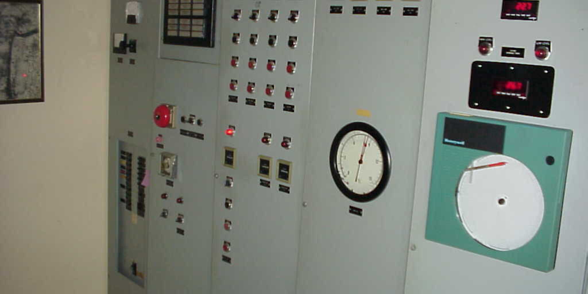
The control system is PLC-based, using an Allen Bradley ControlLogix 5000 with an Operator Interface Terminal for local display, indication, alarm, and trending, and Numatics distributed control at the valve racks. The new filters run in conjunction with the existing pressure filters and wells to hold a target elevation in the finished water storage tank, with the new VFD effluent pump and later pump additions paced in a lead, lag, and lag-lag arrangement – clamped to a minimum flow of roughly 1.0 MGD, with a pump-on / pump-off deadband to prevent cycling. At the clearwell, a falling level progressively calls the microfiltration system, then the existing lead pressure filters, then the wells, then the existing lag pressure filters for emergency standby, and sheds them in reverse order as the level recovers. High-discharge-pressure shutdowns protect the pumps, high and low level alarms cover the tank and clearwell, and off-site alarming is grouped into priority and secondary tiers through a smart autodialer. The new PLC operates the new filters, issues call-to-run commands to the existing pressure filters and wells, and provides supervisory monitoring of the existing filters’ status and alarms.
HMI, SCADA, and Telemetry
The design incorporates an HMI/SCADA system built on an Intellution iFIX HMI running on a PC at the water treatment plant, with PLC remote units of the same manufacturer at the finished water storage tank and the outlying monitoring and pump sites – the Feather River, Larkin Road (Airport), and 5th Street flow-monitoring stations and the Link Side Pump Station. Communication uses non-licensed, frequency-hopping, spread-spectrum radio, pathing from the remote sites to a repeater at the finished water storage tank and from there to the master station at the plant control building; the links were verified by field survey. The HMI integrates display, logging, indication, alarming, and report generation for the new and existing filters, and the system’s details were carried into a dedicated SCADA telemetry design report prepared as part of the upgrade.
Key Technical Elements
| Parameter | Detail |
| Plant Capacity | 4 MGD microfiltration, up to 4.8 MGD sustained; a phased step toward an ultimate 20 MGD plant |
| Treatment Process | Pall membrane microfiltration, replacing alum-based pressure filtration |
| Existing Plant | 6 MGD pressure filters (two banks of three, 3 MGD each), 1 MGD clearwell, raw water pump station, ~170,000 gpd backwash to unlined settling ponds |
| Raw Water Pump | 125 HP, pumping through the microfilter modules directly to the clearwell |
| Membrane Support | Two reverse-filtration pumps and two compressors (10 HP each at the 4 MGD stage; upsizable for later expansion) |
| Control System | PLC-based Allen Bradley ControlLogix 5000 with Operator Interface Terminal; Numatics distributed control at valve racks |
| Pump Control | VFD lead / lag / lag-lag pacing to hold finished-water-tank and clearwell setpoints; ~1.0 MGD minimum-flow clamp with on/off deadband |
| Source Staging | Level-based staging of the microfiltration system, existing pressure filters, and wells at the clearwell |
| Alarming | High-discharge-pressure pump shutdowns; high/low level alarms; priority/secondary off-site alarm autodialer |
| HMI / SCADA | Intellution iFIX HMI at the plant; PLC remote units at the finished water tank and remote flow-monitoring and pump stations |
| Telemetry | Non-licensed frequency-hopping spread-spectrum radio; repeater at the finished water tank to the master station; field-verified links |
Project Outcome
EETS delivered the design for a 4 MGD membrane microfiltration plant – capable of 4.8 MGD for sustained periods – that replaces alum-based pressure filtration and, by removing the alum coagulant, addresses the aluminum that had built up in the plant’s sludge and soil. The design integrates the new plant with the retained pressure filters, held in standby and emergency roles, and with the District’s supply wells, coordinating all three around shared clearwell and finished-water-tank levels through a single PLC-based control system. A supporting HMI/SCADA and radio telemetry backbone ties the plant to its finished water tank and outlying monitoring and pump stations, and the whole design is structured to extend as the plant grows toward its ultimate 20 MGD capacity.
Value Delivered by EETS
EETS treated the expansion as an environmental fix, a controls-integration problem, and a phased-growth plan at once, and designed for all three.
Solving the Aluminum Problem Through Process Selection
The core value was in the choice of process. Rather than optimize a filtration approach whose own coagulant was the source of the contamination, EETS designed the plant around membrane microfiltration, which treats without alum. That single decision is what makes it possible to bring the aluminum concentration in the sludge back toward virgin-soil levels – an outcome the existing alum-based process could never reach – and EETS carried it through into a full, buildable design rather than leaving it as a recommendation.
Making Three Supply Sources Behave as One Plant
The engineering that ties the plant together is in its controls. EETS designed a PLC-based system that stages the new microfiltration plant, the existing pressure filters, and the wells against shared clearwell and finished-water-tank levels, paces VFD pumps in a lead/lag/lag-lag sequence with a minimum-flow clamp and anti-cycling deadband, and protects the whole with pressure shutdowns and tiered off-site alarms. The result is a multi-source plant that holds its target levels and keeps the older filters available without an operator constantly balancing it by hand.
Designed for the Plant It Will Become
The design does not treat 4 MGD as the finish line. The reverse-filtration pumps and compressors are sized to be swapped for larger units at later expansions, the control logic already accommodates additional pumps in its staging sequence, and the HMI/SCADA and radio telemetry backbone – with remote units across the finished water tank and outlying stations, and a dedicated telemetry design report – gives the District an infrastructure that grows with the plant on its path to 20 MGD, rather than one that has to be rebuilt at the next expansion.
Drink
As part of this expansion, AWA identified an opportunity to recover energy that was previously being wasted.