
69kV Greenfield Substation and Ground Grid Design
Amazon Automation Facility | California

Project Overview
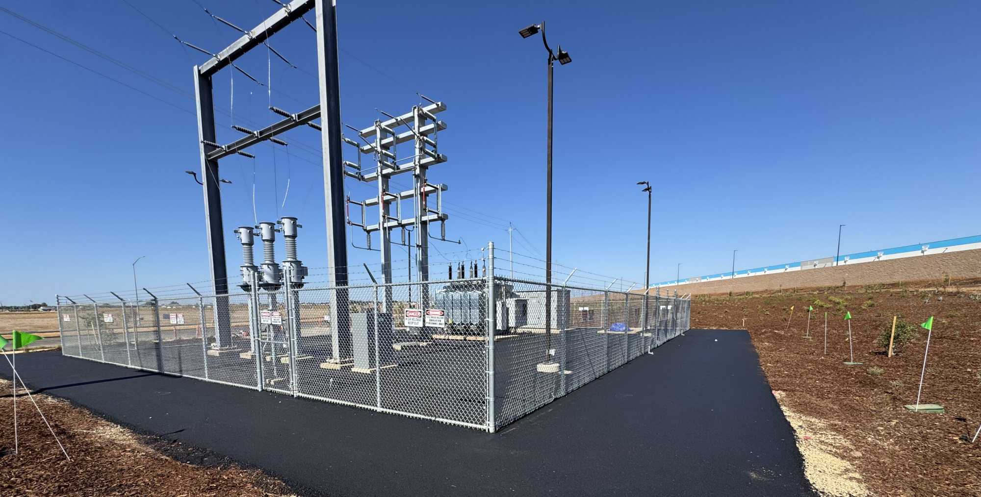
EETS designed a new 69kV air insulated substation and associated 12.47kV distribution system to serve a 750,000 square foot Amazon automation facility in California. The substation serves as the facility’s sole source of electrical power and connects to the local utility’s 69kV transmission system.
A critical component of any substation design is the grounding system. A properly engineered ground grid protects both personnel and equipment by ensuring that voltage differences between any two accessible points, including step potentials between a person’s feet, and touch potentials between a person and energized equipment, remain within safe limits during a fault condition. EETS designed and analyzed the grounding system in accordance with IEEE Std 80, “Guide for Safety in AC Substation Grounding,” using SKM Power Tools ground grid analysis software.
What began as a well-defined engineering task became one of the most technically demanding ground grid investigations EETS has encountered, one that required persistent field investigation, creative problem solving, and a surface treatment strategy that challenged conventional substation design assumptions.
Project Challenge
A Soil Resistivity Discrepancy That Stopped the Project in Its Tracks
Soil resistivity is the single most important input in ground grid design. It governs how effectively fault current dissipates into the earth and directly determines whether step and touch potentials will fall within safe limits. The higher the resistivity, the less current the soil can absorb, and the more robust the ground grid must be to compensate.
At project outset, EETS was provided a soil resistivity value to use in the initial ground grid model. The value, measured at 10,450 ohm-cm (approximately 104.5 ohm-m), appeared reasonable and was represented as a current measurement for the site. Using this figure, along with the fault current data supplied by the local utility at the 69kV point of interconnection, EETS modeled the substation footprint with all equipment locations established and designed a comprehensive ground grid.
The initial design featured:
- 250 kcmil bare copper conductors on an approximate 10.4 by 10.9 foot grid spacing
- 43 copper-clad steel ground rods, each 3/4 inch in diameter and 10 feet in length, with 14-foot rods at each grid corner
- A grid burial depth of 24 inches below finished grade
- A grid footprint of approximately 92 by 98 feet, extending a minimum of 3 feet beyond the perimeter fence and past the full swing radius of each gate
The design passed step and touch potential analysis under the provided soil conditions and was submitted to the utility for review.
The utility’s review raised a critical flag: they requested independent field verification of the soil resistivity to confirm it matched the value used in the analysis. When field testing was conducted, the results did not match. The discrepancy was not minor; it was substantial. Repeated field testing returned a maximum apparent resistivity of 267.40 ohm-m, more than two and a half times the value originally provided.
After extensive investigation, the source of the discrepancy was identified. The resistivity value originally furnished to EETS had been measured in 2005, before the site had undergone lime stabilization as part of site preparation for construction. Lime treatment is a common soil improvement technique, but it significantly alters the soil’s electrical properties. The treated soil presented a far higher resistivity than the original 2005 measurement suggested, rendering the initial design inadequate.
This discovery, made after the ground grid had already been installed and substation equipment had been set in place, created a serious engineering and schedule problem. Every month of delay directly postponed energization of a 750,000 square foot facility.
Client
Amazon
Sector
Private / Industrial
Location
California
Services
Power Engineering Design | Substation Engineering | Grounding System Analysis

Drink
As part of this expansion, AWA identified an opportunity to recover energy that was previously being wasted.
Client
Amazon
Sector
Private / Industrial
Location
California
Services
Power Engineering Design | Substation Engineering | Grounding System Analysis
Drink
As part of this expansion, AWA identified an opportunity to recover energy that was previously being wasted.
Project Overview
EETS designed a new 69kV air insulated substation and associated 12.47kV distribution system to serve a 750,000 square foot Amazon automation facility in California. The substation serves as the facility’s sole source of electrical power and connects to the local utility’s 69kV transmission system.
A critical component of any substation design is the grounding system. A properly engineered ground grid protects both personnel and equipment by ensuring that voltage differences between any two accessible points, including step potentials between a person’s feet, and touch potentials between a person and energized equipment, remain within safe limits during a fault condition. EETS designed and analyzed the grounding system in accordance with IEEE Std 80, “Guide for Safety in AC Substation Grounding,” using SKM Power Tools ground grid analysis software.
What began as a well-defined engineering task became one of the most technically demanding ground grid investigations EETS has encountered, one that required persistent field investigation, creative problem solving, and a surface treatment strategy that challenged conventional substation design assumptions.
Project Challenge
A Soil Resistivity Discrepancy That Stopped the Project in Its Tracks
Soil resistivity is the single most important input in ground grid design. It governs how effectively fault current dissipates into the earth and directly determines whether step and touch potentials will fall within safe limits. The higher the resistivity, the less current the soil can absorb, and the more robust the ground grid must be to compensate.
At project outset, EETS was provided a soil resistivity value to use in the initial ground grid model. The value, measured at 10,450 ohm-cm (approximately 104.5 ohm-m), appeared reasonable and was represented as a current measurement for the site. Using this figure, along with the fault current data supplied by the local utility at the 69kV point of interconnection, EETS modeled the substation footprint with all equipment locations established and designed a comprehensive ground grid.
The initial design featured:
- 250 kcmil bare copper conductors on an approximate 10.4 by 10.9 foot grid spacing
- 43 copper-clad steel ground rods, each 3/4 inch in diameter and 10 feet in length, with 14-foot rods at each grid corner
- A grid burial depth of 24 inches below finished grade
- A grid footprint of approximately 92 by 98 feet, extending a minimum of 3 feet beyond the perimeter fence and past the full swing radius of each gate
The design passed step and touch potential analysis under the provided soil conditions and was submitted to the utility for review.
The utility’s review raised a critical flag: they requested independent field verification of the soil resistivity to confirm it matched the value used in the analysis. When field testing was conducted, the results did not match. The discrepancy was not minor; it was substantial. Repeated field testing returned a maximum apparent resistivity of 267.40 ohm-m, more than two and a half times the value originally provided.
After extensive investigation, the source of the discrepancy was identified. The resistivity value originally furnished to EETS had been measured in 2005, before the site had undergone lime stabilization as part of site preparation for construction. Lime treatment is a common soil improvement technique, but it significantly alters the soil’s electrical properties. The treated soil presented a far higher resistivity than the original 2005 measurement suggested, rendering the initial design inadequate.
This discovery, made after the ground grid had already been installed and substation equipment had been set in place, created a serious engineering and schedule problem. Every month of delay directly postponed energization of a 750,000 square foot facility.
Engineering Solution
Diagnosing the Problem Before Designing the Fix
With the correct soil resistivity established at 267.40 ohm-m, EETS re-ran the ground grid analysis to understand the full scope of what needed to be resolved. The model confirmed what the field data suggested: the existing ground grid, as installed, would not achieve safe step and touch potentials under the actual soil conditions.
The first instinct in this situation, and the instinct EETS tested methodically, is to add more copper. More conductors and more ground rods extend the grid’s ability to dissipate fault current over a larger soil volume. EETS evaluated this approach thoroughly.
The analysis produced an important and non-obvious insight: no practical quantity of additional below-grade copper would meaningfully reduce the step and touch potentials to within safe limits. The soil resistivity was simply too high for the buried conductor network alone to overcome. The relationship between added copper and improved potentials had become effectively non-linear; each incremental addition yielded diminishing returns that fell far short of what was needed.
This finding redirected the engineering focus from what was below the surface to what was above it.
The Surface Treatment Strategy
IEEE Std 80 recognizes that surface material resistivity plays a direct role in limiting the current a person can experience during a fault. A high-resistivity surface layer acts as an insulating barrier between personnel and the ground grid, dramatically increasing the impedance of the path through a person’s body and reducing the tolerable shock current to safe levels.
The original design had incorporated 4 inches of crushed stone with a resistivity of 3,000 ohm-m throughout the substation yard. EETS determined that this value, while common in substation design, was not sufficient given the site’s elevated soil resistivity.
EETS investigated alternative surface materials and identified hot mix asphalt as a viable solution, contingent on confirming its actual electrical resistivity through laboratory testing. A sample of the project’s asphalt mix was submitted for testing, where it was tested in accordance with ASTM G1877 methods. The tested specimen returned a resistivity greater than 4,207,206 ohm-cm, exceeding the meter’s upper measurement limit, confirming that the asphalt would provide a dramatically more effective insulating surface than crushed stone.
EETS specified a two-layer surface system for the substation yard:
- A 2-inch compacted aggregate base layer
- A 4-inch hot mix asphalt top layer, with a minimum specified resistivity of 15,000 ohm-m
To address step potentials beyond the substation fence, where personnel and the public could potentially walk, EETS extended 5 feet of crushed stone (3,000 ohm-m) outward from the asphalt edge on all four sides of the substation. This transitional zone was analyzed out to 50 feet beyond the fence line to confirm safety for anyone in the surrounding area.
The asphalt was also extended a minimum of 42 inches beyond the end of each gate when positioned perpendicular to the fence, ensuring that touch potential protection remained in place for personnel entering or exiting the substation.
Key Technical Elements
Parameter | Detail |
Voltage Standard | IEEE Std 80 (2013), 50 kg body weight (conservative) |
Fault Current | Line-to-ground fault of 3,705 A at 69kV; maximum clearing time 0.516 seconds |
Division Factor | 1.0 applied (100% of fault current into grid, worst-case assumption) |
Soil Resistivity (Corrected) | 267.40 ohm-m, single-layer homogeneous model for substation interior |
Ground Grid Conductor | 250 kcmil annealed soft-drawn copper, approximately 1,793 lineal feet total |
Ground Rods | 43 copper-clad steel rods, 3/4″ diameter, approximately 446 lineal feet total |
Grid Burial Depth | 24 inches below finished grade |
Asphalt Resistivity (Tested) | Greater than 42,072 ohm-m, confirmed by Cooper Testing Labs (ASTM G1877) |
Surface System | 2-inch compacted aggregate base + 4-inch hot mix asphalt; 5-foot crushed stone perimeter beyond asphalt edge |
Analysis Software | SKM Ground Mat Version 2.0.2.8 |
Field-Measured Ground Resistance | 1.39 ohms post-asphalt vs. 3.68 ohms calculated (conservative model confirmed) |
Project Outcome
Following the surface treatment modification, EETS completed a comprehensive grounding system study and submitted it to the utility for final review. The results confirmed that the design met all required safety standards with meaningful margin:
Parameter | Permissible Limit | Calculated Value |
Touch Voltage, Main Feed | 7,244 V | 2,346 V |
Step Voltage, Main Feed | 28,492 V | 1,094 V |
Touch Voltage, Alternate Feed | 4,096 V | 1,423 V |
Step Voltage, Alternate Feed | 16,110 V | 663 V |
In every case, the calculated voltages were well within the permissible limits. The utility approved the design, the substation was energized, and the Amazon automation facility was brought online, approximately six months after the soil discrepancy first came to light.
Value Delivered by EETS
This project demonstrates what separates experienced power engineering from routine design work. When a material error in the foundational soil data invalidated the original design after construction had already begun, and EETS did not simply add copper and submit a revised report. Instead, the team investigated until they understood precisely why the grid was underperforming, identified the actual controlling variable, and engineered a solution that addressed it directly.
Persistent Root Cause Investigation
EETS did not accept the initial discrepancy at face value. Repeated testing, data reconciliation, and coordination with the utility and geotechnical team ultimately traced the problem to a 20-year-old soil sample that predated lime stabilization of the site, a discovery that required both technical depth and tenacity to uncover.
Recognizing the Limits of the Conventional Approach
Rather than recommending an endless and ultimately ineffective expansion of the below-grade grid, EETS quantified the non-linear relationship between additional copper and safety improvement, and made the engineering call to redirect the solution to the surface layer.
Laboratory-Validated Material Selection
The decision to specify asphalt was backed by actual resistivity testing of the project’s specific mix, not published assumptions. This gave the utility a defensible, data-supported basis for approval.
Conservative, Well-Documented Analysis
By applying a fault current division factor of 1.0, using the most conservative soil data available, and omitting the aggregate base layer from the model, EETS ensured that the final design remained safe even under conditions more severe than what would realistically occur in the field.
The substation now operates reliably at the heart of a major logistics and automation facility, and the grounding system meets or exceeds every applicable safety standard, despite the significant field challenges encountered during construction.
Drink
As part of this expansion, AWA identified an opportunity to recover energy that was previously being wasted.