
ENGINEERING CASE STUDY
100 MVA Data Center Substation: Ground Grid Design and Third-Party Engineering Review
Apple Inc. | Mills Substation | Washoe County, Nevada
Project Overview
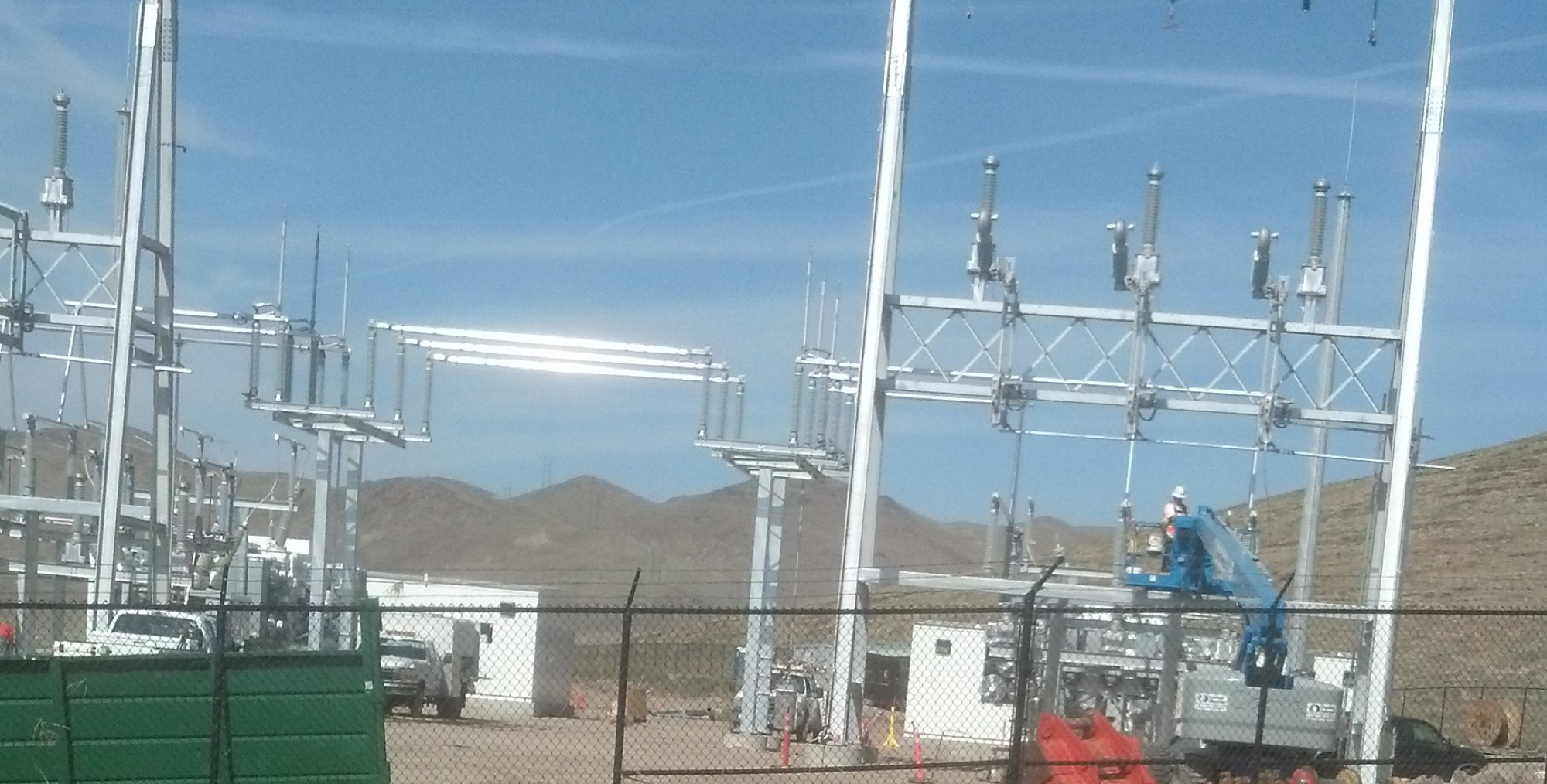
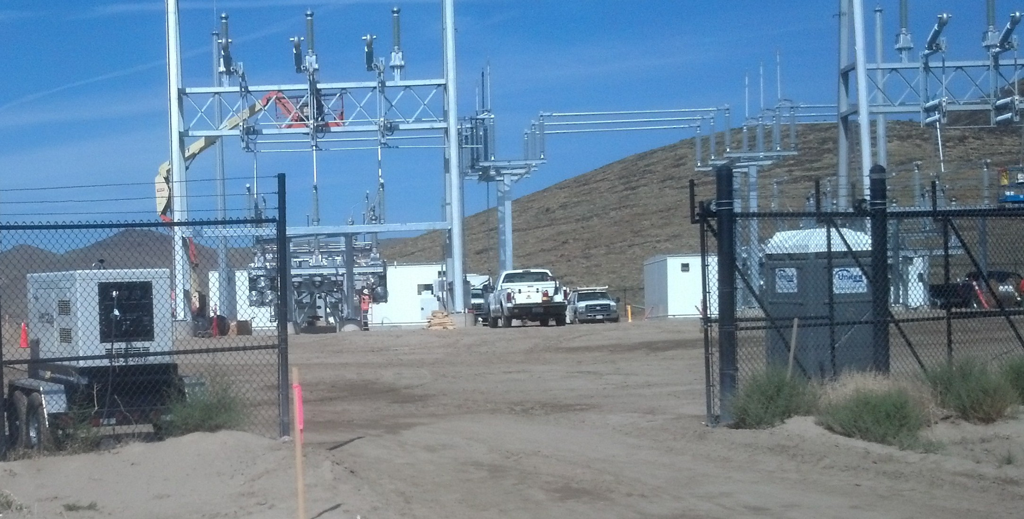
In 2013, Apple announced plans for a major expansion of its data center campus near Reno, Nevada. The Mills Substation was a critical component of that expansion, providing the additional power supply infrastructure needed to support Apple’s growing iCloud, iTunes, App Store, and related digital services. The 22,500 square foot, 100 MVA substation connects via overhead 120kV lines to a new NV Energy switching station, with the substation itself constructed by Apple and the switching yard by NV Energy.
The project was fast-tracked from the outset, with an unusually compressed schedule driven by Apple’s urgent need to bring the Mills Diablo building online. That building would consume all remaining available power at the property, making the new substation the prerequisite for any further campus expansion. Schedule slippage was not an option.
EETS was engaged to provide targeted engineering services on this design-build project, including third-party review of the substation design prepared by the prime engineering firm, ground grid design and stamped calculations, cable thermal ampacity analysis for the medium voltage feeders between the substation and the data center, short circuit and coordination studies, arc flash analysis, one-line and relaying drawings, point-to-point interconnection drawings, and construction management and startup support.
Ground Grid Design
Two Compounding Challenges
The Mills Substation ground grid presented two simultaneous design challenges that, taken together, demanded a more robust and carefully optimized design than a typical 120kV substation would require.
The first challenge was the site’s soil resistivity. Field testing by the geotechnical firm using a four-point Wenner Array configuration revealed a strongly layered soil profile. The upper layer, extending to approximately seven feet below grade, consisted of poorly graded sand with silt at very low moisture content, with a measured resistivity of approximately 25,000 ohm-cm (250 ohm-m). This is a very high resistivity value for a substation site. The lower layer, a sandy silt with significantly higher moisture content, measured approximately 4,000 ohm-cm (40 ohm-m). While the lower layer is more conductive and beneficial for fault current dissipation, the ground grid is primarily installed in the upper layer, where the high resistivity works against the design.
The second challenge was the available fault current. Design criteria required the ground grid to be evaluated against a future available fault current of 30,000 amperes asymmetrical at three cycles with an X/R ratio of 16, converting to 19,450 amperes RMS symmetrical for use in the grid analysis. Nearly 20,000 amperes of symmetrical fault current is a substantial stress on any grounding system, and combined with the high upper-layer soil resistivity, it meant that conventional grid configurations would not achieve safe step and touch potentials without deliberate optimization.
Design Optimization Through Iterative Analysis
EETS performed the ground grid analysis using Paladin DesignBase ground grid software, per IEEE Std 80-2000, with the design iterated to identify where additional investment in copper produced meaningful reductions in touch and step potentials and where it did not.
Grid spacing was tightened from the 15-foot spacing shown in the original contract documents to an average of 12 feet, adjusted around substation footings and containment structures. Analysis confirmed that spacing tighter than 12 feet provided diminishing returns for lowering touch potential and was not warranted. Grid burial depth was increased from the specified minimum of 18 inches to 24 inches, which provided meaningful improvement. Further depth increase showed diminishing returns.
Ground grid conductor was specified at 250 kcmil soft-drawn copper. The high available fault current made a smaller conductor inadvisable due to the risk of thermal damage before fault clearing, per IEEE 80-2000 Tables 5 and 6. Evaluating a larger conductor size of 500 kcmil showed virtually no improvement in touch potential, confirming that increasing horizontal conductor diameter provides minimal benefit once an adequate conductor size has been selected.
Ground rods of 3/4-inch diameter by 10-foot copper-clad steel were used throughout the grid. The design analysis confirmed that rods longer than 10 feet provide only marginal additional benefit in practice, as driving rods fully vertically beyond that depth is difficult to achieve reliably in the field. Additional rods at the standard length were more effective than fewer longer rods.
A two-inch asphaltic concrete surface layer was specified for the substation yard. Asphaltic concrete has a substantially higher electrical resistivity than the crushed rock commonly used in substation surfacing, and its use meaningfully increases the allowable touch and step voltage limits without requiring additional copper below grade. A current division factor of 1.0 was applied throughout the analysis, assuming no credit for supplemental grounding through the overhead ground wires of the incoming transmission lines. This conservative assumption ensures the design performs safely even if the supplemental grounding system is unavailable or its parameters are uncertain.
The final design configuration consisted of an average 12-foot grid spacing over a 157-foot by 157-foot footprint, 24-inch burial depth, 250 kcmil copper conductors, 130 ground rods, a two-inch asphaltic concrete surface layer, and a current division factor of 1.0. The analysis confirmed a maximum calculated touch voltage of 2,192 volts against an allowable limit of 2,284 volts, with step potential well within limits. The design passed all IEEE Std 80-2000 criteria. Ground potential rise was calculated at 5,697 volts, with a grid resistance of 0.41 ohms.
Cable Thermal Ampacity Analysis
EETS also performed a 15kV class cable thermal ampacity analysis for the medium voltage duct bank between the substation switchgear and the data center load, using the Neher-McGrath method. The specified cable was 1,000 kcmil compressed stranded copper, MV105-rated with EPR insulation, copper tape shield, and overall PVC jacket, installed three conductors per conduit in a six-conduit duct bank arranged two-high by three-wide in Schedule 80 PVC. The concrete encasement backfill surrounding the duct bank was specified at a thermal resistivity of 0.65 degrees C-m/W to manage heat dissipation from the tightly grouped cable bundle.
The native soil at the site presented a significant thermal challenge. Geotechnical testing confirmed the native sandy soil had an as-found thermal resistivity of 2.94 degrees C-m/W, an extremely high value that severely limits the ability of surrounding soil to transfer heat away from buried cables. This required EETS to evaluate numerous duct bank spacing and backfill cross-sectional area configurations to arrive at a design that achieved the required ampacity within the thermal constraints imposed by the native soil. The final design yielded a limiting ampacity of 401 amps per duct, for a combined duct bank capacity of 2,406 amps across all six ducts. This is essentially 100 percent of the 50 MVA transformer secondary full load current of 2,405 amps at 12kV, confirming the duct bank was sized precisely to the load requirement with no thermal limit exceeded.
Third-Party Engineering Review
In addition to the ground grid and cable thermal work, EETS performed a third-party peer review of the substation design drawings and specifications prepared by the prime engineering firm. This review evaluated design efficiency and completeness across the full substation electrical design, including one-line diagrams, relaying drawings, and point-to-point interconnection drawings. Short circuit, coordination, and arc flash studies were developed and used to verify the adequacy of protective device selections and settings. EETS also provided CT saturation calculations for the 12kV feeder CT circuit with the longest run, and DC load calculations to verify the battery system and charger sizing for relevant breaker operation and tripping scenarios.
Client
Apple Inc.
Sector
Private / Technology
Location
Washoe County, Nevada
Services
Ground Grid Design and Analysis | Cable Thermal Ampacity Analysis | Third-Party Engineering Review | Short Circuit, Coordination, and Arc Flash Studies | Construction Management and Startup Support

Drink
As part of this expansion, AWA identified an opportunity to recover energy that was previously being wasted.
Client
Apple Inc.
Sector
Private / Technology
Location
Washoe County, Nevada
Services
Ground Grid Design and Analysis | Cable Thermal Ampacity Analysis | Third-Party Engineering Review | Short Circuit, Coordination, and Arc Flash Studies | Construction Management and Startup Support
Drink
As part of this expansion, AWA identified an opportunity to recover energy that was previously being wasted.
Project Overview
In 2013, Apple announced plans for a major expansion of its data center campus near Reno, Nevada. The Mills Substation was a critical component of that expansion, providing the additional power supply infrastructure needed to support Apple’s growing iCloud, iTunes, App Store, and related digital services. The 22,500 square foot, 100 MVA substation connects via overhead 120kV lines to a new NV Energy switching station, with the substation itself constructed by Apple and the switching yard by NV Energy.
The project was fast-tracked from the outset, with an unusually compressed schedule driven by Apple’s urgent need to bring the Mills Diablo building online. That building would consume all remaining available power at the property, making the new substation the prerequisite for any further campus expansion. Schedule slippage was not an option.
EETS was engaged to provide targeted engineering services on this design-build project, including third-party review of the substation design prepared by the prime engineering firm, ground grid design and stamped calculations, cable thermal ampacity analysis for the medium voltage feeders between the substation and the data center, short circuit and coordination studies, arc flash analysis, one-line and relaying drawings, point-to-point interconnection drawings, and construction management and startup support.
Ground Grid Design
Two Compounding Challenges
The Mills Substation ground grid presented two simultaneous design challenges that, taken together, demanded a more robust and carefully optimized design than a typical 120kV substation would require.
The first challenge was the site’s soil resistivity. Field testing by the geotechnical firm using a four-point Wenner Array configuration revealed a strongly layered soil profile. The upper layer, extending to approximately seven feet below grade, consisted of poorly graded sand with silt at very low moisture content, with a measured resistivity of approximately 25,000 ohm-cm (250 ohm-m). This is a very high resistivity value for a substation site. The lower layer, a sandy silt with significantly higher moisture content, measured approximately 4,000 ohm-cm (40 ohm-m). While the lower layer is more conductive and beneficial for fault current dissipation, the ground grid is primarily installed in the upper layer, where the high resistivity works against the design.
The second challenge was the available fault current. Design criteria required the ground grid to be evaluated against a future available fault current of 30,000 amperes asymmetrical at three cycles with an X/R ratio of 16, converting to 19,450 amperes RMS symmetrical for use in the grid analysis. Nearly 20,000 amperes of symmetrical fault current is a substantial stress on any grounding system, and combined with the high upper-layer soil resistivity, it meant that conventional grid configurations would not achieve safe step and touch potentials without deliberate optimization.
Design Optimization Through Iterative Analysis
EETS performed the ground grid analysis using Paladin DesignBase ground grid software, per IEEE Std 80-2000, with the design iterated to identify where additional investment in copper produced meaningful reductions in touch and step potentials and where it did not.
Grid spacing was tightened from the 15-foot spacing shown in the original contract documents to an average of 12 feet, adjusted around substation footings and containment structures. Analysis confirmed that spacing tighter than 12 feet provided diminishing returns for lowering touch potential and was not warranted. Grid burial depth was increased from the specified minimum of 18 inches to 24 inches, which provided meaningful improvement. Further depth increase showed diminishing returns.
Ground grid conductor was specified at 250 kcmil soft-drawn copper. The high available fault current made a smaller conductor inadvisable due to the risk of thermal damage before fault clearing, per IEEE 80-2000 Tables 5 and 6. Evaluating a larger conductor size of 500 kcmil showed virtually no improvement in touch potential, confirming that increasing horizontal conductor diameter provides minimal benefit once an adequate conductor size has been selected.
Ground rods of 3/4-inch diameter by 10-foot copper-clad steel were used throughout the grid. The design analysis confirmed that rods longer than 10 feet provide only marginal additional benefit in practice, as driving rods fully vertically beyond that depth is difficult to achieve reliably in the field. Additional rods at the standard length were more effective than fewer longer rods.
A two-inch asphaltic concrete surface layer was specified for the substation yard. Asphaltic concrete has a substantially higher electrical resistivity than the crushed rock commonly used in substation surfacing, and its use meaningfully increases the allowable touch and step voltage limits without requiring additional copper below grade. A current division factor of 1.0 was applied throughout the analysis, assuming no credit for supplemental grounding through the overhead ground wires of the incoming transmission lines. This conservative assumption ensures the design performs safely even if the supplemental grounding system is unavailable or its parameters are uncertain.
The final design configuration consisted of an average 12-foot grid spacing over a 157-foot by 157-foot footprint, 24-inch burial depth, 250 kcmil copper conductors, 130 ground rods, a two-inch asphaltic concrete surface layer, and a current division factor of 1.0. The analysis confirmed a maximum calculated touch voltage of 2,192 volts against an allowable limit of 2,284 volts, with step potential well within limits. The design passed all IEEE Std 80-2000 criteria. Ground potential rise was calculated at 5,697 volts, with a grid resistance of 0.41 ohms.
Cable Thermal Ampacity Analysis
EETS also performed a 15kV class cable thermal ampacity analysis for the medium voltage duct bank between the substation switchgear and the data center load, using the Neher-McGrath method. The specified cable was 1,000 kcmil compressed stranded copper, MV105-rated with EPR insulation, copper tape shield, and overall PVC jacket, installed three conductors per conduit in a six-conduit duct bank arranged two-high by three-wide in Schedule 80 PVC. The concrete encasement backfill surrounding the duct bank was specified at a thermal resistivity of 0.65 degrees C-m/W to manage heat dissipation from the tightly grouped cable bundle.
The native soil at the site presented a significant thermal challenge. Geotechnical testing confirmed the native sandy soil had an as-found thermal resistivity of 2.94 degrees C-m/W, an extremely high value that severely limits the ability of surrounding soil to transfer heat away from buried cables. This required EETS to evaluate numerous duct bank spacing and backfill cross-sectional area configurations to arrive at a design that achieved the required ampacity within the thermal constraints imposed by the native soil. The final design yielded a limiting ampacity of 401 amps per duct, for a combined duct bank capacity of 2,406 amps across all six ducts. This is essentially 100 percent of the 50 MVA transformer secondary full load current of 2,405 amps at 12kV, confirming the duct bank was sized precisely to the load requirement with no thermal limit exceeded.
Third-Party Engineering Review
In addition to the ground grid and cable thermal work, EETS performed a third-party peer review of the substation design drawings and specifications prepared by the prime engineering firm. This review evaluated design efficiency and completeness across the full substation electrical design, including one-line diagrams, relaying drawings, and point-to-point interconnection drawings. Short circuit, coordination, and arc flash studies were developed and used to verify the adequacy of protective device selections and settings. EETS also provided CT saturation calculations for the 12kV feeder CT circuit with the longest run, and DC load calculations to verify the battery system and charger sizing for relevant breaker operation and tripping scenarios.
Key Technical Elements
Parameter | Detail |
Substation Rating | 100 MVA, 120kV to 12kV |
Ground Grid Footprint | 157 feet by 157 feet, extending minimum 3 feet beyond perimeter fence including gate swing radii |
Soil Resistivity (Upper Layer) | 250 ohm-m (poorly graded sand with silt, surface to 7 feet depth) |
Soil Resistivity (Lower Layer) | 40 ohm-m (sandy silt with high moisture content, below 7 feet) |
Design Fault Current | 30,000 A asymmetrical at 3 cycles, X/R = 16; 19,450 A RMS symmetrical |
Grid Conductor | 250 kcmil soft-drawn copper |
Grid Spacing | Average 12 feet, adjusted for substation features |
Grid Burial Depth | 24 inches below subgrade |
Ground Rods | 130 rods, 3/4-inch diameter by 10-foot copper-clad steel |
Surface Material | 2-inch asphaltic concrete |
Current Division Factor | 1.0 (no supplemental grounding credit) |
Maximum Touch Voltage (Calculated) | 2,192 V vs. allowable limit of 2,284 V |
Ground Potential Rise | 5,697 V |
Grid Resistance | 0.41 ohms |
Cable Analysis Method | Neher-McGrath method; 6-conduit 2×3 duct bank, 1,000 kcmil 15kV EPR copper cable; combined ampacity 2,406 A matching 50 MVA transformer full load at 12kV |
Ground Grid Analysis Standard | IEEE Std 80-2000 |
Project Outcome
All EETS deliverables were completed on schedule and on budget, meeting every submission date despite the project’s fast-track demands. The Mills Substation was successfully energized, enabling Apple’s data center campus expansion to proceed. The ground grid design passed IEEE Std 80-2000 criteria with the calculated touch potential confirmed below the allowable limit, and the design’s conservative assumptions provide additional margin for future fault current increases as the NV Energy system continues to develop.
Value Delivered by EETS
This project showcases EETS’s ability to contribute precise, high-stakes engineering deliverables within a fast-track, design-build environment where schedule pressure is constant and the technical margin for error is narrow.
Optimizing a Difficult Ground Grid
The combination of high upper-layer soil resistivity and a nearly 20,000-ampere symmetrical fault current created a ground grid design problem that required genuine engineering judgment, not just calculation. EETS methodically evaluated the effect of grid spacing, burial depth, conductor size, rod length, and asphaltic concrete surface material on touch and step potentials, identifying where tighter parameters produced meaningful improvement and where they did not. The result was a design that passed IEEE Std 80-2000 criteria while remaining constructible and cost-effective, rather than simply specifying more copper until the numbers passed.
Conservative Assumptions That Protect Long-Term Safety
Applying a current division factor of 1.0 and taking no credit for supplemental grounding through the incoming transmission line ground wires are deliberate choices that make the analysis more conservative than strictly required. For a facility of this scale and criticality, that conservatism is appropriate. It ensures the grounding system performs safely even as the surrounding utility system evolves and as fault current levels potentially increase over the life of the substation.
Delivering on a Fast-Track Schedule
Apple’s need to bring the Mills Substation online was urgent and non-negotiable. EETS met every deliverable date across a comprehensive scope of engineering work, from ground grid design to third-party review to construction management support, without requesting schedule extensions. For a client operating at the scale and pace of a major technology company’s infrastructure program, reliable delivery against an aggressive schedule is itself a form of engineering value.
Drink
As part of this expansion, AWA identified an opportunity to recover energy that was previously being wasted.