
Camanche Powerhouse Protective Relay and Switchgear Upgrade
East Bay Municipal Utility District | Camanche Powerhouse | Northern California
Project Overview
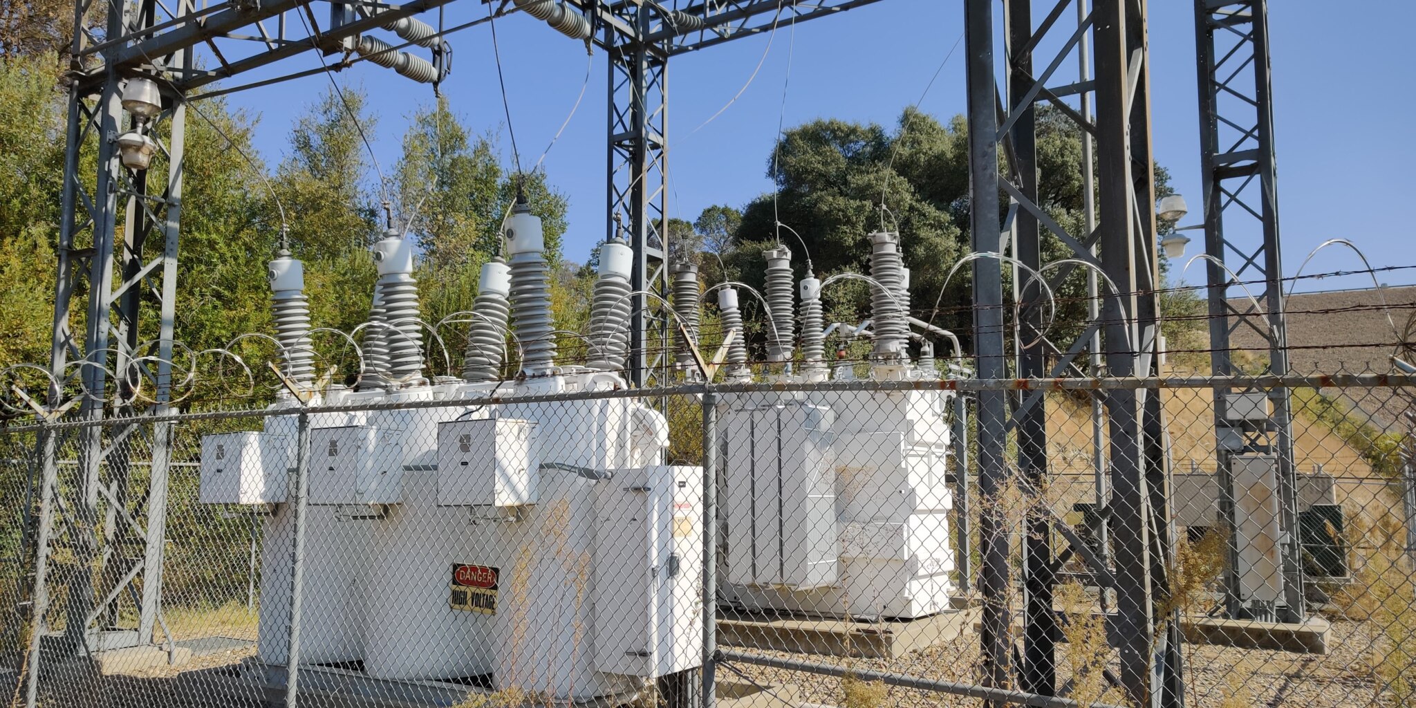
East Bay Municipal Utility District (EBMUD) is a publicly owned utility serving over one million people in the San Francisco East Bay with drinking water, wastewater, and pollution prevention services. Among its assets are two hydroelectric power plants at Pardee and Camanche Reservoirs. The Pardee Powerhouse, originally built in 1928 and expanded in 1983, has a nameplate capacity of 23.6 MW and connects to the grid at 69 kV. The Camanche Powerhouse, commissioned in 1983, has a capacity of 10 MW and interconnects at 115 kV.
The protective relay systems at the Camanche Powerhouse had reached the end of their service life. The majority of the installed relays were electromechanical devices that had been in service since the facility’s original commissioning. Age, limited parts availability, and the growing difficulty of maintaining aging electromechanical technology made a full relay replacement increasingly necessary. EBMUD also had an opportunity to address broader facility needs at the same time: the existing switchgear required a vacuum circuit breaker replacement, NEC live-to-ground clearances on the bus were no longer being met, and the facility lacked arc flash protection and the safety features required for modern maintenance access.
EETS was engaged to provide full electrical engineering design for the relay upgrade and associated switchgear improvements at the Camanche Powerhouse. The scope covered protective relay replacement for three generators and station service, 115 kV line protection for the Camanche substation, vacuum circuit breaker procurement and installation specifications, arc flash sensor and relay integration, and the addition of infrared inspection windows. EETS also developed relay setting files, and coordinated with PG&E on utility interconnection requirements.
The Facility
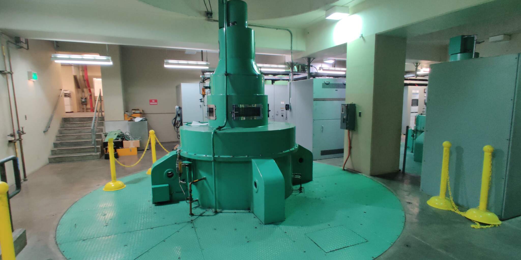
The Camanche Powerhouse operates three synchronous hydroelectric generating units with a combined capacity of 10 MW, interconnected to PG&E’s transmission system at 115 kV through the Camanche substation. The facility had operated with its original electromechanical protection scheme since 1983, supplemented over the decades by various retrofits that had added complexity to the installed wiring without corresponding updates to the as-built documentation.
The replacement protection scheme was designed around SEL digital relays, with redundant relay packages for each of the three generator units and for the 115 kV line protection at the Camanche substation. The 115 kV line relay design incorporated PG&E’s required protective elements, including directional overcurrent and zone distance protection. A dedicated Schweitzer relay control with automatic synchronizing capability was integrated into the protection package for each individual unit, replacing a single shared synchronizer from the 1960s that had become a single point of failure for the entire powerhouse.
Project Challenge
Decoding Four Decades of Field Changes
Replacing electromechanical relays with modern digital devices is conceptually straightforward, but the practical challenge on a facility of this age lies in understanding what the existing system actually does before designing what replaces it. At Camanche, that understanding was not available from the drawings. The as-built documentation for the original installation was poor, and the facility had accumulated decades of field modifications that were never reflected in updated records.
The evidence of those modifications was visible at the terminal blocks throughout the switchgear and relay panels. Standard practice limits a terminal block to two wire landings. At Camanche, it was common to find three, four, or five wires terminated at a single point – a sign that over the years, modifications had been made by adding conductors to existing terminations rather than by revising the wiring design. The original drawings, where they existed at all, did not account for any of these changes. The actual state of the wiring had to be determined by physical investigation.
Recreating the Existing Design Before Replacing It
Designing a replacement protection scheme for the facility required first reconstructing an accurate picture of what the existing scheme was doing. Electromechanical relays implement protection functions through discrete components – coils, contacts, timing mechanisms – wired together into functional circuits. Translating that into a digital relay configuration requires understanding not just which relays were installed, but how the wiring between them defined the actual operating logic. With the as-builts unreliable and the terminal blocks carrying far more connections than the drawings showed, that reconstruction had to be built from the hardware itself.
The stakes of getting this wrong were significant. A protection scheme that fails to replicate critical functions from the original design – or that introduces logic errors in translating those functions into a digital relay configuration – can leave generating equipment unprotected or prevent it from operating correctly. The design work required disciplined tracing and verification before any new configuration could be finalized.
Switchgear Constraints: Breaker Compatibility and Bus Clearances
The existing switchgear at Camanche was built around GE Magnablast air circuit breakers, which rack vertically into their compartments – a configuration specific to that product line and incompatible with modern replacement breakers that use standard horizontal racking. Replacing the entire switchgear lineup was the obvious solution but was not viable: the existing footprint left no room for new gear of equivalent capacity, and the cost and outage duration of a full switchgear replacement would have been substantially greater.
A separate but related problem existed on the bus. Available clearances between live bus and grounded surfaces did not meet NEC requirements. Addressing this within the existing switchgear structure required a solution that restored code-compliant clearances without physical relocation or modification to the switchgear.
A Single Synchronizer for Three Generators
Synchronous generators cannot be connected to the grid without first matching voltage, frequency, and phase angle to the energized system. The Camanche Powerhouse had relied on a single automatic synchronizer, installed in the 1960s, to perform this function for all three generating units. When that device failed, no unit could be brought online. A facility with three generators effectively had the reliability of a facility with one, because the synchronizer was the single point of failure that controlled all of them.
Client
East Bay Municipal Utility District
Sector
Public / Municipal Water and Power
Location
Northern California
Services
Electrical Engineering Design │ Protection and Control │ Switchgear Engineering │ Utility Coordination

Drink
As part of this expansion, AWA identified an opportunity to recover energy that was previously being wasted.
Client
East Bay Municipal Utility District
Sector
Public / Municipal Water and Power
Location
Northern California
Services
Electrical Engineering Design │ Protection and Control │ Switchgear Engineering │ Utility Coordination
Drink
As part of this expansion, AWA identified an opportunity to recover energy that was previously being wasted.
Project Overview
East Bay Municipal Utility District (EBMUD) is a publicly owned utility serving over one million people in the San Francisco East Bay with drinking water, wastewater, and pollution prevention services. Among its assets are two hydroelectric power plants at Pardee and Camanche Reservoirs. The Pardee Powerhouse, originally built in 1928 and expanded in 1983, has a nameplate capacity of 23.6 MW and connects to the grid at 69 kV. The Camanche Powerhouse, commissioned in 1983, has a capacity of 10 MW and interconnects at 115 kV.
The protective relay systems at the Camanche Powerhouse had reached the end of their service life. The majority of the installed relays were electromechanical devices that had been in service since the facility’s original commissioning. Age, limited parts availability, and the growing difficulty of maintaining aging electromechanical technology made a full relay replacement increasingly necessary. EBMUD also had an opportunity to address broader facility needs at the same time: the existing switchgear required a vacuum circuit breaker replacement, NEC live-to-ground clearances on the bus were no longer being met, and the facility lacked arc flash protection and the safety features required for modern maintenance access.
EETS was engaged to provide full electrical engineering design for the relay upgrade and associated switchgear improvements at the Camanche Powerhouse. The scope covered protective relay replacement for three generators and station service, 115 kV line protection for the Camanche substation, vacuum circuit breaker procurement and installation specifications, arc flash sensor and relay integration, and the addition of infrared inspection windows. EETS also developed relay setting files, and coordinated with PG&E on utility interconnection requirements.
The Facility
The Camanche Powerhouse operates three synchronous hydroelectric generating units with a combined capacity of 10 MW, interconnected to PG&E’s transmission system at 115 kV through the Camanche substation. The facility had operated with its original electromechanical protection scheme since 1983, supplemented over the decades by various retrofits that had added complexity to the installed wiring without corresponding updates to the as-built documentation.
The replacement protection scheme was designed around SEL digital relays, with redundant relay packages for each of the three generator units and for the 115 kV line protection at the Camanche substation. The 115 kV line relay design incorporated PG&E’s required protective elements, including directional overcurrent and zone distance protection. A dedicated Schweitzer relay control with automatic synchronizing capability was integrated into the protection package for each individual unit, replacing a single shared synchronizer from the 1960s that had become a single point of failure for the entire powerhouse.
Project Challenge
Decoding Four Decades of Field Changes
Replacing electromechanical relays with modern digital devices is conceptually straightforward, but the practical challenge on a facility of this age lies in understanding what the existing system actually does before designing what replaces it. At Camanche, that understanding was not available from the drawings. The as-built documentation for the original installation was poor, and the facility had accumulated decades of field modifications that were never reflected in updated records.
The evidence of those modifications was visible at the terminal blocks throughout the switchgear and relay panels. Standard practice limits a terminal block to two wire landings. At Camanche, it was common to find three, four, or five wires terminated at a single point – a sign that over the years, modifications had been made by adding conductors to existing terminations rather than by revising the wiring design. The original drawings, where they existed at all, did not account for any of these changes. The actual state of the wiring had to be determined by physical investigation.
Recreating the Existing Design Before Replacing It
Designing a replacement protection scheme for the facility required first reconstructing an accurate picture of what the existing scheme was doing. Electromechanical relays implement protection functions through discrete components – coils, contacts, timing mechanisms – wired together into functional circuits. Translating that into a digital relay configuration requires understanding not just which relays were installed, but how the wiring between them defined the actual operating logic. With the as-builts unreliable and the terminal blocks carrying far more connections than the drawings showed, that reconstruction had to be built from the hardware itself.
The stakes of getting this wrong were significant. A protection scheme that fails to replicate critical functions from the original design – or that introduces logic errors in translating those functions into a digital relay configuration – can leave generating equipment unprotected or prevent it from operating correctly. The design work required disciplined tracing and verification before any new configuration could be finalized.
Switchgear Constraints: Breaker Compatibility and Bus Clearances
The existing switchgear at Camanche was built around GE Magnablast air circuit breakers, which rack vertically into their compartments – a configuration specific to that product line and incompatible with modern replacement breakers that use standard horizontal racking. Replacing the entire switchgear lineup was the obvious solution but was not viable: the existing footprint left no room for new gear of equivalent capacity, and the cost and outage duration of a full switchgear replacement would have been substantially greater.
A separate but related problem existed on the bus. Available clearances between live bus and grounded surfaces did not meet NEC requirements. Addressing this within the existing switchgear structure required a solution that restored code-compliant clearances without physical relocation or modification to the switchgear.
A Single Synchronizer for Three Generators
Synchronous generators cannot be connected to the grid without first matching voltage, frequency, and phase angle to the energized system. The Camanche Powerhouse had relied on a single automatic synchronizer, installed in the 1960s, to perform this function for all three generating units. When that device failed, no unit could be brought online. A facility with three generators effectively had the reliability of a facility with one, because the synchronizer was the single point of failure that controlled all of them.
Engineering Solution
Field Investigation and Design Reconstruction
EETS conducted a thorough field investigation of the existing wiring at the Camanche Powerhouse, tracing conductors through the switchgear and relay panels to establish the actual as-installed configuration. This process documented the crowded terminal block conditions and identified where multiple field modifications had departed from the original design. The result was a reliable basis for understanding what functions the existing relay scheme was performing and how those functions were implemented in hardware.
With the existing design reconstructed, EETS developed the complete replacement design package. This included new one-line, three-line, schematic, elementary, and wiring drawings for both the generator protection upgrades and the 115 kV line relay installation. The new wiring design addressed the terminal block overcrowding from prior retrofits, distributing connections to conform to standard practice and creating a clean, maintainable termination scheme for the new equipment. New interconnect wiring drawings were developed to support installation and provide EBMUD with accurate records going forward.
Relay setting files were developed for all new SEL devices, including the generator protection relays and the 115 kV line relays, with PG&E’s required directional overcurrent and zone distance protection elements incorporated and coordinated to meet interconnection requirements. Specifications were prepared for the vacuum circuit breaker replacement, including a remote racking device, and for the arc flash sensor and relay system, IR inspection windows, and switchgear insulating panels.
Breaker Conversion and Bus Clearance Solutions
Rather than replacing the entire switchgear lineup, EETS specified an Eaton conversion kit designed to fit the existing GE Magnablast stab sockets. The conversion kit provides the mechanical and electrical interface that allows a modern Eaton vacuum breaker to be installed in the existing compartment with standard horizontal racking, eliminating the vertical-rack limitation of the original GE equipment. The existing switchgear structure is retained, while the breakers are replaced with current-production units that are fully supported with modern parts and service. This approach avoided the space and cost constraints that would have made a full switchgear replacement impractical at this site.
The bus clearance deficiency was resolved through EETS’s recommendation to install Glastic insulating panels on the wall facing the rear of the switchgear. Glastic is a fiberglass-reinforced composite material with high dielectric strength, commonly used in switchgear applications to create effective insulating barriers. By applying Glastic panels to the rear wall where live-to-ground clearances were marginal, EETS restored NEC-compliant separation between energized parts and grounded surfaces without requiring any physical relocation of the bus or structural modification to the switchgear.
Per-Unit Automatic Synchronizing
The shared synchronizer arrangement was eliminated by integrating automatic synchronizing capability directly into the Schweitzer relay control assigned to each generating unit. Each unit now has its own dedicated synchronizing function, independent of the other two. If one relay requires maintenance or fails, the remaining units can continue to operate and synchronize to the grid without interruption. The three-generator powerhouse now has the operational independence its generating capacity was always designed to provide.
Key Technical Elements
Parameter | Detail |
Facility | Camanche Powerhouse, 10 MW hydroelectric facility, interconnected at 115 kV |
Generating Units | Three synchronous hydroelectric generators; Schweitzer relay control and automatic synchronizing for each unit |
Existing Relay Technology | Primarily electromechanical relays, installed 1983, aging and difficult to maintain |
Replacement Relay Platform | SEL digital protective relays; redundant configuration for generators and 115 kV line |
115 kV Line Protection | PG&E-required directional overcurrent and zone distance protection; coordinated with utility |
Auto-Synchronizing | Dedicated Schweitzer relay with automatic synchronizing for each of the three units, replacing a single shared synchronizer from the 1960s |
Switchgear Breaker Replacement | Eaton conversion kit retrofitted into existing GE Magnablast stab sockets; accepts modern Eaton vacuum breakers with standard horizontal racking; preserves existing switchgear lineup |
NEC Clearance Solution | Glastic insulating panels specified by EETS on bus to restore live-to-ground clearances within existing switchgear footprint |
Switchgear Safety Improvements | Arc flash sensor and relay; IR inspection windows; remote racking device for vacuum circuit breakers |
Key Design Challenge | Poor as-builts and decades of undocumented field modifications; terminal blocks with 3–5 wire landings versus standard maximum of two |
Project Outcome
The completed design delivers a modern, fully documented protection scheme for the Camanche Powerhouse, replacing equipment that had exceeded its service life with a digital relay platform capable of meeting current utility interconnection requirements and supporting ongoing maintenance. EBMUD receives accurate as-built drawings for the first time in the facility’s history, along with switchgear improvements that address arc flash safety, restore NEC-compliant bus clearances, and enable routine thermal inspection without energized-equipment exposure. Each generating unit now has its own dedicated synchronizing relay, eliminating the single shared synchronizer that had been the facility’s most consequential operational vulnerability.
Value Delivered by EETS
This project required more than relay selection and setting development. It required the investigative work to understand an aging, poorly documented system before a replacement could be responsibly designed, and the engineering judgment to solve three distinct facility problems within the constraints of a structure that could not be replaced.
Reading What the Drawings Could Not Say
The original as-built drawings at Camanche could not be relied on. Decades of field modifications had added wiring and connections that never made it back to the record drawings, leaving the actual state of the protection scheme embedded in the hardware itself. EETS conducted the field investigation necessary to reconstruct that design from the installed equipment, tracing the crowded terminal blocks and undocumented conductors to establish a reliable basis for the replacement. That work is not glamorous, but it is what separates a replacement design grounded in reality from one grounded in assumptions.
Translating Electromechanical Logic into a Digital Platform
Electromechanical relays implement protection through physical components wired into functional circuits. Modern digital relays implement the same functions through software configuration. The translation between these paradigms requires understanding both: knowing what each element of the original scheme was doing and knowing how to replicate that behavior accurately in the replacement platform. EETS brought that understanding to the Camanche design, ensuring that protection functions carried over completely and that the new configuration added the capabilities – redundancy, per-unit automatic synchronizing, arc flash protection, and NEC-compliant bus insulation – that the original scheme lacked.
Solving Within the Existing Footprint
Three of the most consequential problems at Camanche – obsolete breakers, inadequate bus clearances, and a single-point-of-failure synchronizer – each had an expensive, disruptive obvious solution: replace the switchgear, relocate the bus, replace the synchronizer panel. EETS found a better path in each case. The Eaton conversion kit preserved the existing switchgear structure while delivering modern breaker technology. Glastic panels on the switchgear rear wall restored NEC clearances without moving anything. Integrating synchronizing into each unit’s Schweitzer relay eliminated the shared synchronizer without adding new panel equipment. The result is a facility that has been substantially modernized within the physical and financial constraints of what was already there.
Creating the Record the Facility Never Had
The new drawing package EETS developed – one-lines, three-lines, schematics, elementaries, and wiring drawings for both the generator protection and 115 kV line relay installations – gives EBMUD accurate documentation of the Camanche Powerhouse electrical systems for the first time since the original installation. That record will support safe, efficient maintenance and future modifications for the life of the facility. Cleaning up the terminal block wiring as part of the new design ensures that future engineers and technicians will not face the same reconstruction challenge that this project required.
Drink
As part of this expansion, AWA identified an opportunity to recover energy that was previously being wasted.