
3rd Street Bore Cable Thermal Ampacity Analysis
San Francisco Public Utilities Commission | 3rd Street Bore | San Francisco, California
Project Overview
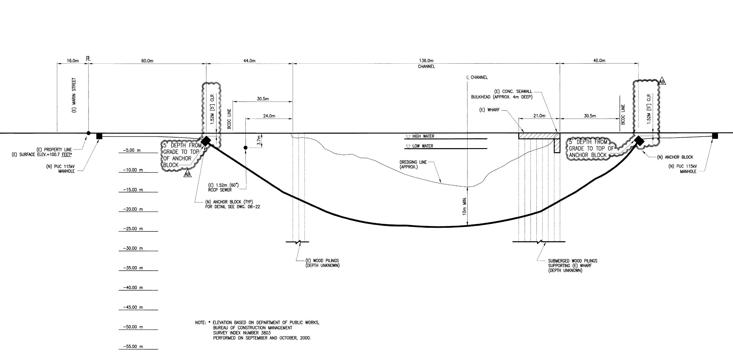
The San Francisco Public Utilities Commission planned to route 35 kV distribution circuits through an existing bore crossing beneath 3rd Street in San Francisco. The bore consisted of HDPE pipe installed underground, through which conduits carrying the 35 kV cables would be pulled. Two alternative pipe configurations were under consideration: a single 42-inch pipe, and two 30-inch pipes installed side by side. Before committing to either configuration, SFPUC needed to know whether the proposed cable installation could carry the required load capacity within the thermal limits of the cable insulation system.
EETS was engaged by AECOM, the prime consultant on the project, to perform thermal ampacity calculations for both pipe configurations using the Neher-McGrath method. The Neher-McGrath method is the established engineering approach for calculating the current-carrying capacity of underground cables, accounting for the thermal resistivity of the surrounding soil, the pipe infill material, the conduit arrangement, mutual heating between adjacent loaded conductors, and the cable construction itself. The calculations were performed using Paladin DesignBase with the Cable Ampacity IEC/Neher-McGrath module, with soil thermal resistivity, pipe infill resistivity, and ambient temperature values provided by AECOM from site-specific data.
The Cable System and Design Parameters
The cables specified for the crossing are 35 kV class, single conductor, 750 kcmil copper compressed segmented conductors, rated MV-105 with 133% insulation level, EPR insulation, copper tape shield, and PVC jacket. Three conductors are installed per 6-inch conduit, one per phase. The cable construction determines the thermal resistance between the conductor and the conduit wall, which is a key input to the ampacity calculation. The maximum allowable conductor temperature is 90°C, and each active circuit must be capable of carrying a minimum of 14 MVA at 34.5 kV. Soil parameters provided by AECOM established a native soil thermal resistivity of 1.5°C-m/W, a pipe infill thermal resistivity of 0.6°C-m/W, and an ambient soil temperature of 30°C at the bore depth of 10 feet below grade.
Project Challenge
Mutual Heating in a Confined Pipe Crossing
Underground cable ampacity is fundamentally a heat transfer problem. A conductor carrying current generates heat in proportion to its resistance and the square of the current. That heat must flow outward through the insulation, the conduit wall, the pipe infill, and the surrounding soil before it reaches a thermal sink. The maximum allowable current is the current at which the conductor temperature reaches its rated limit while all of that thermal resistance is accounted for. When multiple loaded cables occupy the same pipe, each cable contributes heat to the shared thermal environment, raising the temperature that every other cable must dissipate against. The more cables loaded simultaneously, and the closer they are to one another, the greater the mutual heating effect and the lower the individual cable ampacity.
The bore crossing configuration concentrated multiple loaded conduits within a single large pipe, creating a thermal environment that had to be modeled accurately to determine whether the 14 MVA design criterion could be met. The worst-case loading condition assumed by AECOM placed one circuit at 100% of loop load (a contingency condition with one side of a loop failed) while five adjacent circuits carried 50% of loop load simultaneously, maximizing the mutual heating effect on the most heavily loaded circuit.
Modeling Two Adjacent Pipes Simultaneously
The two-pipe scenario presented a modeling challenge that the available software could not resolve directly. Paladin DesignBase could not simultaneously simulate the thermal interaction between two adjacent loaded 30-inch pipes, each containing active circuits contributing heat to the shared soil environment between them. The thermal influence of one pipe on the other, separated by only 18 inches of native soil, was a real physical effect that the analysis had to capture, but the software had no mechanism to model it directly.
Client
Sector
Public / Municipal Utility
Location
San Francisco, California
Services
Cable Thermal Ampacity Analysis │ Neher-McGrath Calculations │ Multi-Scenario Pipe Crossing Study │ Design Recommendations

Drink
As part of this expansion, AWA identified an opportunity to recover energy that was previously being wasted.
Client
Sector
Public / Municipal Utility
Location
San Francisco, California
Services
Cable Thermal Ampacity Analysis │ Neher-McGrath Calculations │ Multi-Scenario Pipe Crossing Study │ Design Recommendations
Drink
As part of this expansion, AWA identified an opportunity to recover energy that was previously being wasted.
Project Overview
The San Francisco Public Utilities Commission planned to route 35 kV distribution circuits through an existing bore crossing beneath 3rd Street in San Francisco. The bore consisted of HDPE pipe installed underground, through which conduits carrying the 35 kV cables would be pulled. Two alternative pipe configurations were under consideration: a single 42-inch pipe, and two 30-inch pipes installed side by side. Before committing to either configuration, SFPUC needed to know whether the proposed cable installation could carry the required load capacity within the thermal limits of the cable insulation system.
EETS was engaged by AECOM, the prime consultant on the project, to perform thermal ampacity calculations for both pipe configurations using the Neher-McGrath method. The Neher-McGrath method is the established engineering approach for calculating the current-carrying capacity of underground cables, accounting for the thermal resistivity of the surrounding soil, the pipe infill material, the conduit arrangement, mutual heating between adjacent loaded conductors, and the cable construction itself. The calculations were performed using Paladin DesignBase with the Cable Ampacity IEC/Neher-McGrath module, with soil thermal resistivity, pipe infill resistivity, and ambient temperature values provided by AECOM from site-specific data.
The Cable System and Design Parameters
The cables specified for the crossing are 35 kV class, single conductor, 750 kcmil copper compressed segmented conductors, rated MV-105 with 133% insulation level, EPR insulation, copper tape shield, and PVC jacket. Three conductors are installed per 6-inch conduit, one per phase. The cable construction determines the thermal resistance between the conductor and the conduit wall, which is a key input to the ampacity calculation. The maximum allowable conductor temperature is 90°C, and each active circuit must be capable of carrying a minimum of 14 MVA at 34.5 kV. Soil parameters provided by AECOM established a native soil thermal resistivity of 1.5°C-m/W, a pipe infill thermal resistivity of 0.6°C-m/W, and an ambient soil temperature of 30°C at the bore depth of 10 feet below grade.
Project Challenge
Mutual Heating in a Confined Pipe Crossing
Underground cable ampacity is fundamentally a heat transfer problem. A conductor carrying current generates heat in proportion to its resistance and the square of the current. That heat must flow outward through the insulation, the conduit wall, the pipe infill, and the surrounding soil before it reaches a thermal sink. The maximum allowable current is the current at which the conductor temperature reaches its rated limit while all of that thermal resistance is accounted for. When multiple loaded cables occupy the same pipe, each cable contributes heat to the shared thermal environment, raising the temperature that every other cable must dissipate against. The more cables loaded simultaneously, and the closer they are to one another, the greater the mutual heating effect and the lower the individual cable ampacity.
The bore crossing configuration concentrated multiple loaded conduits within a single large pipe, creating a thermal environment that had to be modeled accurately to determine whether the 14 MVA design criterion could be met. The worst-case loading condition assumed by AECOM placed one circuit at 100% of loop load (a contingency condition with one side of a loop failed) while five adjacent circuits carried 50% of loop load simultaneously, maximizing the mutual heating effect on the most heavily loaded circuit.
Modeling Two Adjacent Pipes Simultaneously
The two-pipe scenario presented a modeling challenge that the available software could not resolve directly. Paladin DesignBase could not simultaneously simulate the thermal interaction between two adjacent loaded 30-inch pipes, each containing active circuits contributing heat to the shared soil environment between them. The thermal influence of one pipe on the other, separated by only 18 inches of native soil, was a real physical effect that the analysis had to capture, but the software had no mechanism to model it directly.
Engineering Solution
Scenario A: Single 42-Inch Pipe
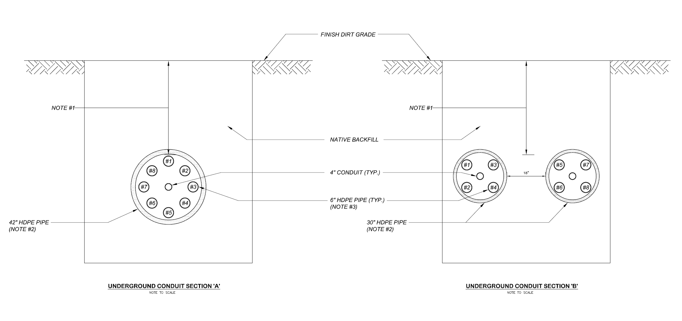
For the single 42-inch pipe scenario, EETS modeled all eight 6-inch conduits within the pipe, with six carrying active 34.5 kV circuits and two left as spares, along with two 4-inch non-power conduits. The conduit positions within the pipe were modeled at their actual geometric locations as shown in the duct bank cross-section drawing. The six active conduits were loaded according to the worst-case contingency condition specified by AECOM, with Cables 3 through 8 loaded at varying proportions to simulate one circuit at full loop load with the remaining circuits at 50% load. Cables 1 and 2 were the spare conduits, modeled at zero load, which also had the effect of introducing some asymmetry in the thermal environment of the loaded cables near them.
The Neher-McGrath model converged after 12 iterations. The most thermally constrained active cable reached a minimum ampacity of 269A, equivalent to 16.07 MVA at 34.5 kV, which exceeds the 14 MVA design criterion. All six active circuits exceeded the criterion, with individual circuit capacities ranging from 16.07 MVA to 17.63 MVA depending on position within the pipe.
Scenario B: Two 30-Inch Pipes with External Heat Source Modeling
To address the software limitation in modeling two adjacent pipes simultaneously, EETS developed a conservative workaround: one of the two 30-inch pipes was represented as an external heat source at a specified temperature, and the model was run with that heat source temperature varied across four increments: 35°C, 40°C, 45°C, and 50°C. This approach approximated the thermal influence of the second loaded pipe on the modeled pipe across a realistic range of operating temperatures, without requiring the software to simulate both pipe systems simultaneously. Running the analysis across the full temperature range provided both a conservative bound and a central estimate of the actual thermal interaction between the two pipes in service.
At the most conservative condition modeled (50°C external heat source), the minimum active circuit ampacity was 292A, equivalent to 17.45 MVA, which still exceeds the 14 MVA design criterion. At the least conservative condition modeled (35°C external heat source), the minimum ampacity was 334A, equivalent to 19.96 MVA. The study also established that cable capacity only falls below the 14 MVA threshold when the external heat source exceeds 65°C, a condition EETS identified as extreme and not representative of realistic operating conditions. The model converged in 8 iterations across all four temperature runs.
Key Technical Elements
Parameter | Detail |
Client | San Francisco Public Utilities Commission (end owner); AECOM (prime consultant) |
Study Type | 35 kV cable thermal ampacity calculations using the Neher-McGrath method; Paladin DesignBase 5.0 / Cable Ampacity IEC/Neher-McGrath Version 5.50 |
Cable Specification | 35 kV, single conductor, 750 kcmil copper compressed segmented, MV-105-rated, 133% insulation level, EPR insulation, copper tape shield, PVC jacket; three conductors per conduit |
Design Criteria | Minimum 14 MVA capacity per circuit at 34.5 kV; maximum conductor temperature 90°C |
Scenario A | One 42-inch HDPE pipe; 8 × 6-inch PVC conduits (6 active, 2 spare) plus 2 × 4-inch non-power conduits; 10 feet below grade |
Scenario A Result | Minimum capacity 269A (16.07 MVA); all six active circuits exceed the 14 MVA design criterion |
Scenario B | Two 30-inch HDPE pipes at 18-inch separation; 4 × 6-inch conduits per pipe (3 active, 1 spare) plus 1 × 4-inch non-power conduit; 10 feet below grade |
Scenario B Modeling | Software limitation for dual-pipe simulation resolved by replacing one pipe with a variable external heat source at 35°C, 40°C, 45°C, and 50°C increments |
Scenario B Result | Minimum capacity 292A (17.45 MVA) at 50°C external source; 334A (19.96 MVA) at 35°C; capacity falls below 14 MVA only above 65°C external source (extreme case, not representative of real-world conditions) |
Conclusion | Single 42-inch pipe provides lower construction cost; two 30-inch pipes offer 4 to 17% greater cable capacity but require a minimum 6.5-foot wide trench at 10-foot depth |
Recommendations | Fluidized thermal backfill at 0.6°C-m/W around pipes to minimize cable derating; cable ampacity would increase if ambient soil temperature is 25°C rather than the assumed 30°C |
Project Outcome
Both pipe configurations were confirmed to provide sufficient thermal ampacity to meet the 14 MVA design criterion under the specified worst-case loading conditions. The single 42-inch pipe delivered a minimum circuit capacity of 16.07 MVA. The two 30-inch pipes delivered a minimum of 17.45 MVA even under the most conservative thermal interaction assumption modeled, and would not fall below the design criterion unless the adjacent pipe reached 65°C, a condition outside the range of realistic operating scenarios. EETS’s analysis also recommended that fluidized thermal backfill be used around the pipes to minimize cable derating and noted that a reduction in ambient soil temperature from the assumed 30°C to 25°C would further increase available ampacity. The study gave SFPUC and AECOM a technically grounded basis for choosing between the two pipe options, with the single 42-inch pipe identified as the lower-cost construction solution despite providing somewhat less cable capacity.
Value Delivered by EETS
Cable thermal ampacity in a pipe crossing is not a standard lookup table calculation. It requires modeling the actual geometry of the installation, the thermal properties of every material in the heat flow path, and the loading pattern across all cables sharing the same thermal environment. Getting it right matters: an overly conservative result could eliminate a viable design option on cost grounds, while an optimistic result could lead to an installation that cannot carry its rated load without overheating the cable insulation.
Neher-McGrath Expertise for a Non-Standard Installation
The 3rd Street bore is not a standard duct bank installation. Multiple large-diameter cables sharing a single oversized HDPE pipe, with a conduit spacer arrangement that places each circuit at a specific geometric position relative to its neighbors, creates a thermal environment that must be modeled in detail rather than estimated from handbook derating tables. EETS applied the Neher-McGrath method to this specific geometry using the actual conduit positions from the duct bank cross-section drawing, producing ampacity results that reflected the actual thermal conditions each circuit would face rather than a conservative generic estimate.
A Practical Workaround for a Software Limitation
The two-pipe scenario could not be modeled directly in the available software. Rather than reporting that the analysis could not be performed or making unsupported assumptions about the thermal interaction between the two pipes, EETS developed a structured workaround: representing the second pipe as a variable external heat source and running the model at four temperature increments across a realistic operating range. This approach produced a bounded result rather than a single-point estimate, allowing EETS to confirm that the design criterion was met not just at one assumed condition but across the full envelope of plausible interactions between the two pipes. The analysis also identified the threshold at which capacity would fall below the design criterion, giving SFPUC a clear picture of the margin available in the two-pipe configuration.
A Technically Grounded Decision Basis
The study did not simply confirm that both configurations worked. It quantified the difference between them: the two-pipe option offered 4 to 17% greater cable capacity than the single-pipe option, but required a substantially larger trench at a depth where excavation cost is significant. By delivering accurate ampacity numbers for both configurations alongside a clear statement of the construction cost trade-off, EETS gave SFPUC and AECOM a technically grounded basis for making a decision that involved both engineering and economic considerations. That is what a useful engineering study delivers: not just a pass/fail answer, but the information needed to make the right choice.
Drink
As part of this expansion, AWA identified an opportunity to recover energy that was previously being wasted.