
230 kV GIS Substation Power System Study
San Francisco Public Utilities Commission | ‘L1T’ Substation Analysis | San Francisco, California

Project Overview
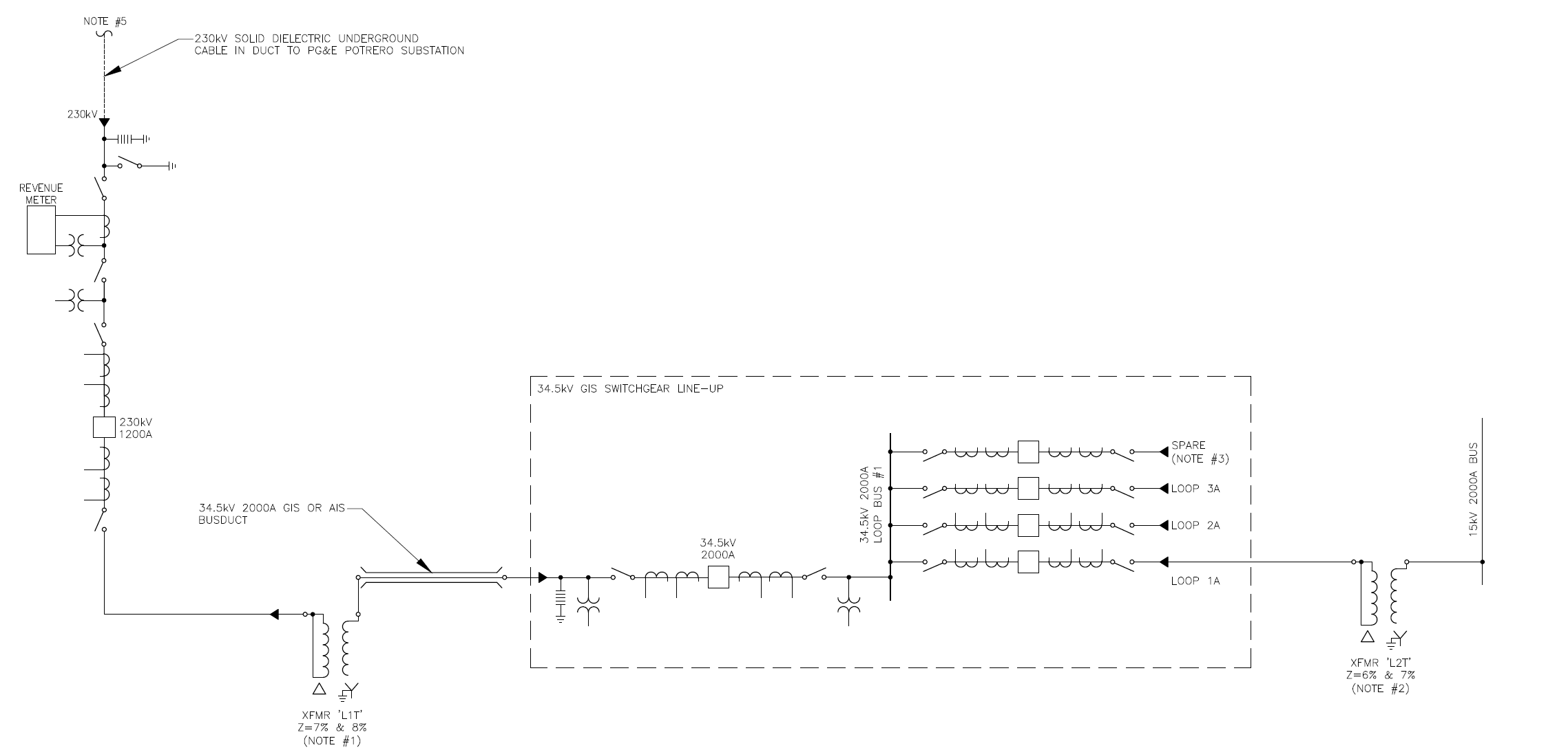
The San Francisco Public Utilities Commission (SFPUC) planned a new ‘L1T’ substation as part of its Bay Corridor Transmission and Distribution program, delivered through the Hetch Hetchy Water and Power enterprise. The substation is sourced from PG&E’s Potrero substation through a 6,200-foot 230 kV underground cable, which feeds a lineup of 230 kV gas-insulated switchgear (GIS). The 230 kV GIS in turn feeds a 230:34.5 kV, 45/60/75 MVA transformer designated ‘L1T’, which supplies a lineup of 34.5 kV GIS. The 34.5 kV switchgear feeds a 34.5:12.47 kV transformer ‘L2T’, rated either 20 MVA or 25 MVA. Both constant-power loads and inductive motor loads are connected at the 34.5 kV and 12.47 kV buses.
SFPUC engaged EETS to perform the power system engineering study for the new substation. The objective was to determine power losses, voltage drop, and the available fault current at points throughout the system, and to use those results to establish whether specific corrective equipment – shunt reactors, current limiting reactors, power factor correction capacitors, and a transformer load tap changer – would be required. The analysis consisted of a short circuit study and a load flow study.
To capture the range of conditions the substation would actually see in service, EETS grouped the study results into seven case scenarios, varying transformer ratings, transformer impedances, and loading so that equipment decisions would hold across the full operating envelope rather than at a single design point.
The L1T Substation Configuration
The substation was modeled as a three-voltage system. At the 230 kV level, the source is PG&E’s Potrero substation, delivered over a 6,200-foot underground cable to a 230 kV GIS lineup. The 45/60/75 MVA ‘L1T’ transformer steps 230 kV down to 34.5 kV, feeding a 34.5 kV GIS lineup that both serves distribution loads and supplies the ‘L2T’ transformer down to 12.47 kV. Because the arrangement uses long high-voltage cable and gas-insulated switchgear at two voltage levels, both fault duty and voltage regulation had to be examined carefully at each bus.
The seven scenarios spanned ‘L1T’ transformer impedances of 7% and 8% and ‘L2T’ impedances of 6% and 7%, both L2T ratings of 20 MVA and 25 MVA, and a source voltage swing of ±10% about the nominal 230 kV. Constant-power loads were modeled at 0.90 power factor and inductive motor loads at 0.85, with correction targeted to 0.95. This matrix let EETS test each candidate piece of equipment against the worst case it would encounter.
Project Challenge
Specifying Only the Equipment the System Actually Needs
Corrective equipment on a substation of this kind – shunt reactors, current limiting reactors, power factor correction capacitors, and load tap changers – carries real cost, footprint, and, in some cases, side effects. A current limiting reactor, for example, lowers fault current but introduces additional voltage drop. Specifying equipment that is not required wastes capital and space; failing to specify equipment that is required leaves the system exposed to under-rated devices or poor voltage and power factor. The challenge was to resolve each of these questions definitively rather than defaulting to conservative over-specification.
Holding the Answer Across a Wide Operating Envelope
The source voltage from PG&E was expected to swing ±10%, the transformer impedances and ratings were not yet fixed, and loading would vary from light to full at both distribution buses. Fault current, voltage drop, and power factor all move with these variables. An equipment decision that looked correct at nominal conditions could fail at the extremes, so the study had to demonstrate the right answer across the entire matrix of source voltage, impedance, rating, and load.
Client
San Francisco Public Utilities Commission (SFPUC) – Hetch Hetchy Water and Power
Sector
Public / Municipal Utility
Location
San Francisco, California
Services
Power System Analysis │ Short Circuit Study │ Load Flow Study │ Equipment Requirement Evaluation │ Substation Engineering Support

Drink
As part of this expansion, AWA identified an opportunity to recover energy that was previously being wasted.
Client
San Francisco Public Utilities Commission (SFPUC) – Hetch Hetchy Water and Power
Sector
Public / Municipal Utility
Location
San Francisco, California
Services
Power System Analysis │ Short Circuit Study │ Load Flow Study │ Equipment Requirement Evaluation │ Substation Engineering Support
Drink
As part of this expansion, AWA identified an opportunity to recover energy that was previously being wasted.
Project Overview
The San Francisco Public Utilities Commission (SFPUC) planned a new ‘L1T’ substation as part of its Bay Corridor Transmission and Distribution program, delivered through the Hetch Hetchy Water and Power enterprise. The substation is sourced from PG&E’s Potrero substation through a 6,200-foot 230 kV underground cable, which feeds a lineup of 230 kV gas-insulated switchgear (GIS). The 230 kV GIS in turn feeds a 230:34.5 kV, 45/60/75 MVA transformer designated ‘L1T’, which supplies a lineup of 34.5 kV GIS. The 34.5 kV switchgear feeds a 34.5:12.47 kV transformer ‘L2T’, rated either 20 MVA or 25 MVA. Both constant-power loads and inductive motor loads are connected at the 34.5 kV and 12.47 kV buses.
SFPUC engaged EETS to perform the power system engineering study for the new substation. The objective was to determine power losses, voltage drop, and the available fault current at points throughout the system, and to use those results to establish whether specific corrective equipment – shunt reactors, current limiting reactors, power factor correction capacitors, and a transformer load tap changer – would be required. The analysis consisted of a short circuit study and a load flow study.
To capture the range of conditions the substation would actually see in service, EETS grouped the study results into seven case scenarios, varying transformer ratings, transformer impedances, and loading so that equipment decisions would hold across the full operating envelope rather than at a single design point.
The L1T Substation Configuration
The substation was modeled as a three-voltage system. At the 230 kV level, the source is PG&E’s Potrero substation, delivered over a 6,200-foot underground cable to a 230 kV GIS lineup. The 45/60/75 MVA ‘L1T’ transformer steps 230 kV down to 34.5 kV, feeding a 34.5 kV GIS lineup that both serves distribution loads and supplies the ‘L2T’ transformer down to 12.47 kV. Because the arrangement uses long high-voltage cable and gas-insulated switchgear at two voltage levels, both fault duty and voltage regulation had to be examined carefully at each bus.
The seven scenarios spanned ‘L1T’ transformer impedances of 7% and 8% and ‘L2T’ impedances of 6% and 7%, both L2T ratings of 20 MVA and 25 MVA, and a source voltage swing of ±10% about the nominal 230 kV. Constant-power loads were modeled at 0.90 power factor and inductive motor loads at 0.85, with correction targeted to 0.95. This matrix let EETS test each candidate piece of equipment against the worst case it would encounter.
Project Challenge
Specifying Only the Equipment the System Actually Needs
Corrective equipment on a substation of this kind – shunt reactors, current limiting reactors, power factor correction capacitors, and load tap changers – carries real cost, footprint, and, in some cases, side effects. A current limiting reactor, for example, lowers fault current but introduces additional voltage drop. Specifying equipment that is not required wastes capital and space; failing to specify equipment that is required leaves the system exposed to under-rated devices or poor voltage and power factor. The challenge was to resolve each of these questions definitively rather than defaulting to conservative over-specification.
Holding the Answer Across a Wide Operating Envelope
The source voltage from PG&E was expected to swing ±10%, the transformer impedances and ratings were not yet fixed, and loading would vary from light to full at both distribution buses. Fault current, voltage drop, and power factor all move with these variables. An equipment decision that looked correct at nominal conditions could fail at the extremes, so the study had to demonstrate the right answer across the entire matrix of source voltage, impedance, rating, and load.
Engineering Solution
Short Circuit Study
EETS modeled the power system using all known devices within the scope of the study, calculated three-phase, line-to-line, line-to-ground, and double line-to-ground fault currents at each piece of equipment, and compared the worst-case values against equipment and protective-device interrupting ratings. The available fault current at PG&E’s Potrero substation was 11,589 A, well within the 50 kA interrupting rating typical of 230 kV class circuit breakers.
Current limiting reactor: The highest 34.5 kV fault current, 9,396 A in select study scenarios, sits well below the 40 kA interrupting rating typical of 38 kV medium-voltage GIS, and below the 12.5 kA rating of SFPUC’s downstream padmount and submersible equipment. At 12.47 kV, the calculated fault duty of 252.2 MVA in a select scenario established that 15 kV switchgear with a minimum 500 MVA interrupting rating is required. Because every device was adequately rated for the calculated duties, EETS concluded that a current limiting reactor is not required.
Load Flow, Voltage, and Power Factor Study
The load flow analysis examined voltage and power factor across the same scenarios, at both the 34.5 kV and 12.47 kV buses, under varying source voltage and load. As expected, voltage variance and reactive power loss grew as inductive load increased.
Shunt reactor: With the 230 kV breaker open and no connected load at the maximum anticipated 242 kV source, the voltage at the end of the 6,200-foot cable rose only to 242.68 kV – a change of 0.28%. Because the voltage rise from cable shunt capacitance is minimal even under this worst case, a shunt reactor is not required.
Transformer load tap changer (LTC): Select scenarios clearly indicated that an LTC is required on transformer ‘L1T’. At a 218 kV source, the 34.5 kV bus dropped to as low as 27.45 kV (a 20.43% voltage drop) and the 12.47 kV bus to as low as 9.84 kV (a 21.08% drop). Under light load the same LTC operates to limit voltage rise at the 34.5 kV switchgear.
Power factor correction capacitor: At the 34.5 kV bus the uncorrected power factor fell to 0.89 at 218 kV and 230 kV sources and 0.85 at 242 kV, all below the desired 0.95. To correct this across varying load, EETS specified a two-stage power factor correction capacitor at 34.5 kV, switching 7.5 MVAR in the first stage and 15 MVAR in the second, so that correction can track inductive load as it appears.
Key Technical Elements
Parameter | Detail |
Source & Cable | PG&E Potrero 230 kV substation via 6,200-foot 230 kV underground cable; available fault current 11,589 A |
230 kV System | 230 kV gas-insulated switchgear (GIS) lineup |
Transformer ‘L1T’ | 230:34.5 kV, 45/60/75 MVA; assumed impedance 7% and 8%; load tap changer required |
Transformer ‘L2T’ | 34.5:12.47 kV, 20 MVA or 25 MVA; assumed impedance 6% and 7% |
34.5 kV System | 34.5 kV GIS; highest fault current 9,396 A vs. 40 kA typical rating |
12.47 kV System | Fault duty 252.2 MVA; 15 kV switchgear rated ≥ 500 MVA required |
Shunt Reactor | Not required; cable voltage rise only 0.28% at 242 kV, no-load |
Current Limiting Reactor | Not required; all equipment adequately rated for calculated fault duties |
Power Factor Correction | Two-stage capacitor at 34.5 kV: 7.5 MVAR + 15 MVAR, correcting to 0.95 |
Study Scope | Short circuit and load flow analysis across seven scenarios; ±10% source voltage swing |
EETS Role | Power system engineering study; equipment requirement determination |
Project Outcome
The study gave SFPUC a clear, defensible set of equipment requirements for the new L1T substation. A load tap changer is required on the ‘L1T’ transformer to hold distribution voltage across the ±10% source swing, and a two-stage 7.5/15 MVAR power factor correction capacitor is required at the 34.5 kV bus to reach the 0.95 target. A shunt reactor and a current limiting reactor were both shown to be unnecessary, and all evaluated equipment – including the 15 kV switchgear, which must carry a minimum 500 MVA interrupting rating – was confirmed to be adequately rated for the calculated fault duties. With these results in hand, SFPUC could procure correctly rated equipment and avoid the cost and footprint of devices the system did not need.
Value Delivered by EETS
EETS brought analytical rigor, cost discipline, and independent verification to the equipment decisions behind a new 230 kV substation.
Decisions Proven Across the Full Operating Envelope
Rather than checking equipment at a single design point, EETS built a seven-scenario matrix that varied source voltage, transformer impedance and rating, and loading. Each candidate device – reactor, capacitor, and tap changer – was tested against the worst case it would actually encounter. That is why the study’s conclusions hold: they were reached at the extremes of the operating range, not just at nominal conditions.
Avoiding Unnecessary Capital and Footprint
Two of the four candidate devices, a shunt reactor and a current limiting reactor, were shown to be unnecessary. Ruling them out with quantified evidence – a 0.28% cable voltage rise and fault duties comfortably within equipment ratings – spared SFPUC the cost, space, and, in the case of the current limiting reactor, the added voltage drop those devices would have introduced, while still confirming the LTC and capacitors the system genuinely needs.
Independent Verification That De-risks Procurement
By calculating fault duties at every bus and comparing them against interrupting ratings, EETS confirmed that the 230 kV breakers, 34.5 kV GIS, downstream padmount and submersible equipment, and 12.47 kV switchgear are all correctly rated before those items were purchased and installed. Establishing the minimum 500 MVA rating for the 15 kV switchgear is one example of a specification the owner could carry straight into procurement with confidence.
Drink
As part of this expansion, AWA identified an opportunity to recover energy that was previously being wasted.