
Power Factor and Reactive Power Study for a Wind Farm
Sacramento Municipal Utility District (SMUD) | Solano Wind Farm Power Factor Analysis | Montezuma Hills, California
Project Overview
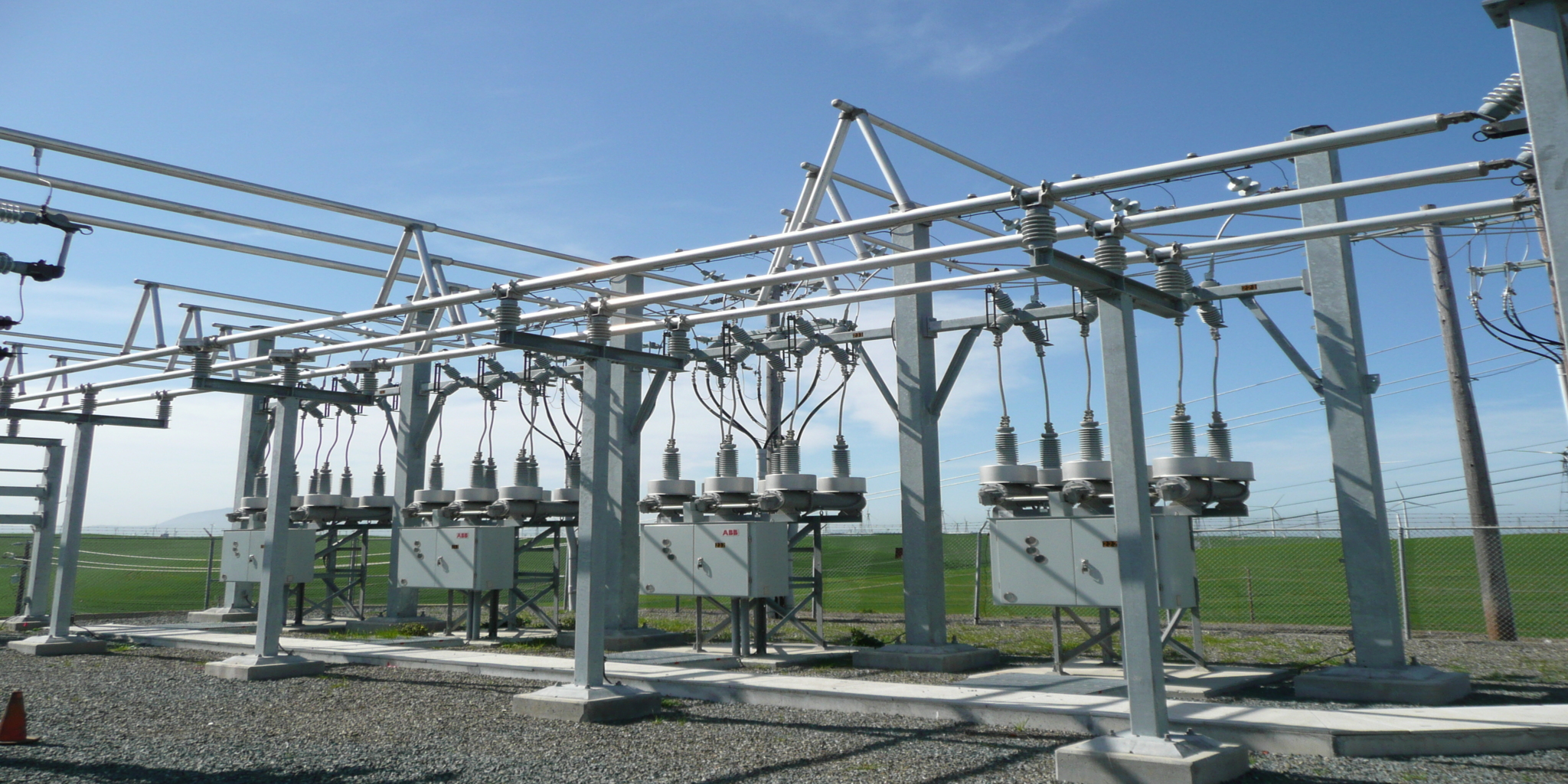
SMUD’s Solano Wind Farm comprises 23 Vestas V47 turbines rated 660 kW and 29 Vestas V90 turbines rated 3,000 kW. Their output flows through 21 kV underground collector cables and overhead heavy-feeder circuits – numbered #5 through #8 – to Russell Substation, where the 230:21 kV transformer ‘T2’ connects the farm to the grid. Under its interconnection agreement, SMUD must maintain a 0.995 power factor at the 230 kV side of T2.
The farm was not meeting that requirement. Running its turbines at unity power factor, the collective power factor was about 0.977 at peak output, and the pattern of reactive-power (VAR) flow – pushed from the substation out to the farm – was loading the feeder cables heavily enough to threaten curtailment of real-power generation. SMUD engaged EETS to analyze the reactive behavior of the entire collector and feeder system and recommend how to meet the power-factor requirement and relieve the feeder constraint.
EETS’s analysis produced a two-part answer graduated by cost: an operational change to the turbines that does most of the work for free, and a targeted capacitor addition to close the remaining gap to full compliance.
Where the VARs Come From
The reactive problem is a matter of who supplies what. The overhead distribution feeder segments, the turbine step-up transformers, and the turbines’ own parasitic motor loads all demand reactive power; the 21 kV underground collector and feeder cables, by contrast, are net generators of VARs through their capacitance – but the overhead feeders dominate, so the system is a net VAR consumer. With the V90 turbines running at unity power factor, none of that reactive demand was being served locally, so all of it had to be imported from Russell Substation.
At full generation and unity power factor, EETS calculated the farm’s total load at roughly 102 MW and 22.5 MVAR inductive – about 0.977 power factor – with metered VAR demand possibly higher still. The V90 units, however, are designed to operate anywhere between 0.96 (absorbing VARs) and 0.98 (producing VARs) and were simply not being used to generate the reactive power the system needed.
Project Challenge
A Strict Interconnection Power Factor the Farm Could Not Hold
Meeting 0.995 at T2’s 230 kV terminals requires VARs to flow into the transformer from the 21 kV bus – the reverse of what was happening, with VARs flowing out to the farm. Substation RTU data put T2 at about 0.981 power factor, short of the requirement. Complicating matters, the farm’s power factor moves with output: under unity operation it ranged from about 0.935 at 25% generation to 0.977 at full output. Any fix had to hold across that whole range, not just at one operating point.
Reactive Flow Overloading the Feeder Cables
The imported VARs were not free of consequence. The current that carries them shares the feeder conductors with the real-power current, and under unity-power-factor operation the paired 1000 kcmil aluminum underground getaway cables on circuits #7 and #8 were loaded to roughly 849 amps against an 836-amp rating – over capacity. Left unaddressed, that left only one option to stay within the cables’ rating: curtail real-power generation to make room for the VAR flow. The reactive problem had become a real-power problem.
Client
Sacramento Municipal Utility District (SMUD)
Sector
Public / Municipal Utility – Wind Generation
Location
Solano Wind Farm, Montezuma Hills, California
Services
Power Factor Analysis │ Reactive Power (VAR) Study │ Collector and Feeder Modeling │ Capacitor Bank Sizing │ Interconnection Compliance

Drink
As part of this expansion, AWA identified an opportunity to recover energy that was previously being wasted.
Client
Sacramento Municipal Utility District (SMUD)
Sector
Public / Municipal Utility – Wind Generation
Location
Solano Wind Farm, Montezuma Hills, California
Services
Power Factor Analysis │ Reactive Power (VAR) Study │ Collector and Feeder Modeling │ Capacitor Bank Sizing │ Interconnection Compliance
Drink
As part of this expansion, AWA identified an opportunity to recover energy that was previously being wasted.
Project Overview
SMUD’s Solano Wind Farm comprises 23 Vestas V47 turbines rated 660 kW and 29 Vestas V90 turbines rated 3,000 kW. Their output flows through 21 kV underground collector cables and overhead heavy-feeder circuits – numbered #5 through #8 – to Russell Substation, where the 230:21 kV transformer ‘T2’ connects the farm to the grid. Under its interconnection agreement, SMUD must maintain a 0.995 power factor at the 230 kV side of T2.
The farm was not meeting that requirement. Running its turbines at unity power factor, the collective power factor was about 0.977 at peak output, and the pattern of reactive-power (VAR) flow – pushed from the substation out to the farm – was loading the feeder cables heavily enough to threaten curtailment of real-power generation. SMUD engaged EETS to analyze the reactive behavior of the entire collector and feeder system and recommend how to meet the power-factor requirement and relieve the feeder constraint.
EETS’s analysis produced a two-part answer graduated by cost: an operational change to the turbines that does most of the work for free, and a targeted capacitor addition to close the remaining gap to full compliance.
Where the VARs Come From
The reactive problem is a matter of who supplies what. The overhead distribution feeder segments, the turbine step-up transformers, and the turbines’ own parasitic motor loads all demand reactive power; the 21 kV underground collector and feeder cables, by contrast, are net generators of VARs through their capacitance – but the overhead feeders dominate, so the system is a net VAR consumer. With the V90 turbines running at unity power factor, none of that reactive demand was being served locally, so all of it had to be imported from Russell Substation.
At full generation and unity power factor, EETS calculated the farm’s total load at roughly 102 MW and 22.5 MVAR inductive – about 0.977 power factor – with metered VAR demand possibly higher still. The V90 units, however, are designed to operate anywhere between 0.96 (absorbing VARs) and 0.98 (producing VARs) and were simply not being used to generate the reactive power the system needed.
Project Challenge
A Strict Interconnection Power Factor the Farm Could Not Hold
Meeting 0.995 at T2’s 230 kV terminals requires VARs to flow into the transformer from the 21 kV bus – the reverse of what was happening, with VARs flowing out to the farm. Substation RTU data put T2 at about 0.981 power factor, short of the requirement. Complicating matters, the farm’s power factor moves with output: under unity operation it ranged from about 0.935 at 25% generation to 0.977 at full output. Any fix had to hold across that whole range, not just at one operating point.
Reactive Flow Overloading the Feeder Cables
The imported VARs were not free of consequence. The current that carries them shares the feeder conductors with the real-power current, and under unity-power-factor operation the paired 1000 kcmil aluminum underground getaway cables on circuits #7 and #8 were loaded to roughly 849 amps against an 836-amp rating – over capacity. Left unaddressed, that left only one option to stay within the cables’ rating: curtail real-power generation to make room for the VAR flow. The reactive problem had become a real-power problem.
Engineering Solution
Modeling the Reactive Network Element by Element
EETS built the analysis from first principles, calculating the series inductive reactance and shunt capacitive reactance of every element in the system – the turbines’ parasitic motor loads, the generator step-up transformers, and each size of underground collector cable and overhead feeder conductor. From those values it tallied VAR generation and demand for each of the four feeder circuits at 100%, 50%, and 25% generation, under both the existing unity-power-factor operation and a scenario with the V90 units generating VARs at 0.98 leading power factor.
Turning the Turbines into VAR Sources
Because the V90 turbines have excitation control, EETS recommended operating them at 0.98 leading power factor so they generate reactive power rather than leaving it to be imported. Serving the feeder and local VAR demand from the turbines themselves cut the reactive power delivered to the farm at full output from about 22.5 MVAR to roughly 5.2 MVAR and reversed VAR flow in the underground collector system – all with no appreciable change in collector-cable current and, crucially, no new hardware. Most importantly, it reduced the paired 1000 kcmil getaway-cable loading by about 2.5%, bringing circuits #7 and #8 from roughly 849 amps back within their 836-amp capacity and removing the curtailment risk. (The 23 V47 units on circuit #5 run at essentially unity power factor and have no adjustable VAR control, but their smaller connected generation raises no cable-ampacity concern.)
Sizing a Switched Capacitor Bank for Full Compliance
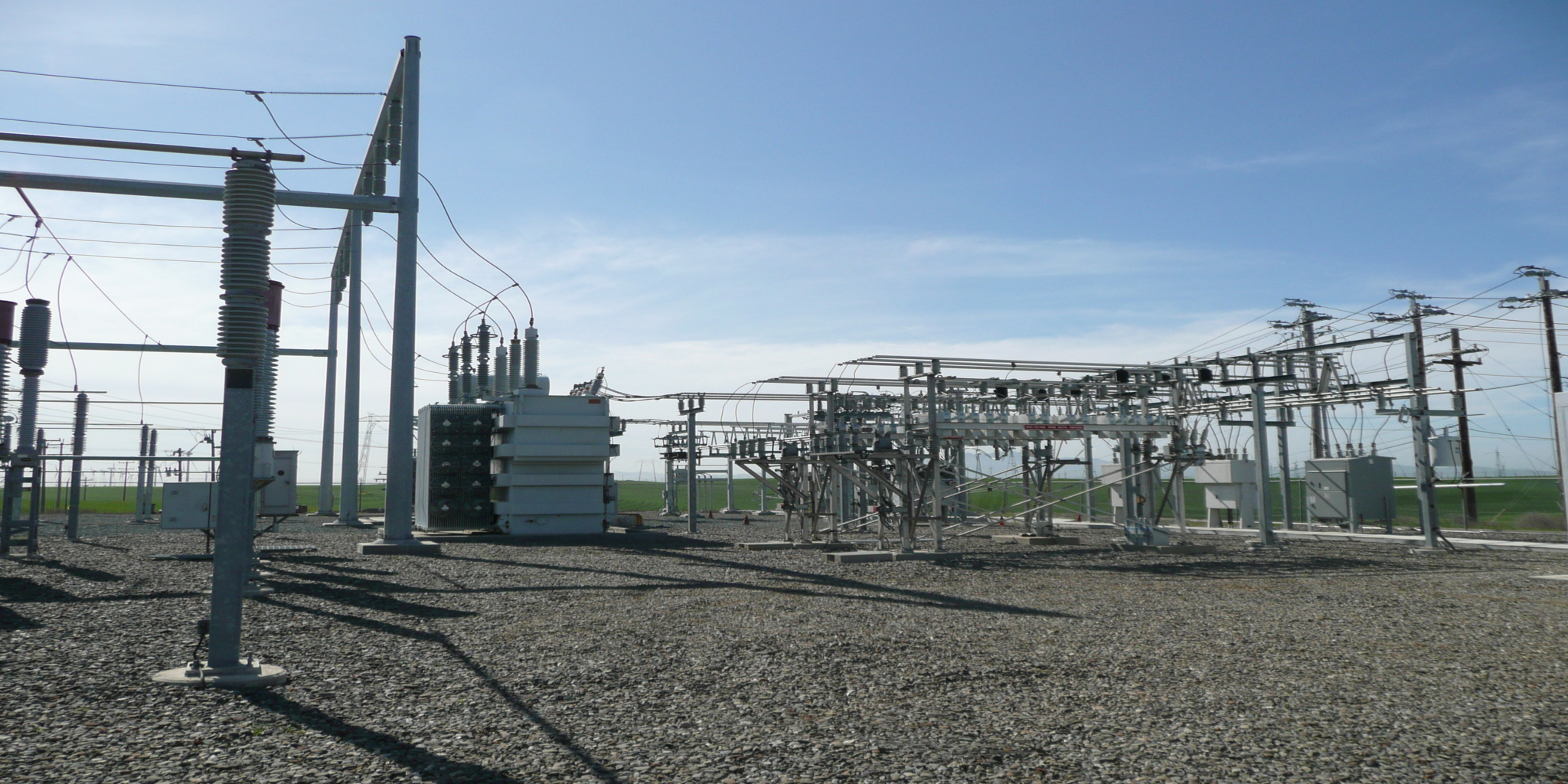
Operating the V90 units at 0.98 leading still leaves a small VAR import at full output, so to hold 0.995 at T2 under all loading conditions EETS recommended adding a capacitor bank of between 7.5 and 17.5 MVAR to the 21 kV T2 bus at Russell Substation. Because the analysis showed the reactive picture inverts at lower output – as generation falls to 50% and 25%, inductive demand drops and net VARs begin flowing back into the substation – EETS specified that the bank be switched, with controls to bring stages in and out at the appropriate load levels, rather than a fixed installation. EETS also flagged that transformer tap settings at individual turbines should be reviewed to keep voltage regulation from full load to no load within limits.
Key Technical Elements
Parameter | Detail |
Wind Farm | 23 × 660 kW Vestas V47 turbines and 29 × 3,000 kW Vestas V90 turbines |
Collector / Feeders | 21 kV underground collectors and overhead heavy-feeder circuits #5–#8 to Russell Substation |
Circuit Loading | #5 = 15.18 MW (23 V47); #6 = 27 MW (9 V90); #7 = 30 MW (10 V90); #8 = 30 MW (10 V90) |
Interconnection Requirement | 0.995 power factor at the 230 kV side of Russell Substation transformer ‘T2’ (230:21 kV, 60/80/100 MVA, 12% Z) |
Measured Power Factor | ≈ 0.977 collective at peak; T2 ≈ 0.981 from substation RTU data |
Reactive Balance | Overhead feeder segments dominate VAR demand; underground cables are net VAR generators; V90 units were running at unity power factor |
Recommendation 1 | Operate V90 units at 0.98 leading power factor (generate VARs) – cuts VAR delivery to the farm from ≈ 22.5 to ≈ 5.2 MVAR at full output |
Cable Relief | Reduces paired 1000 kcmil AL getaway-cable loading ≈ 2.5%, bringing #7/#8 (≈ 849 A) within the 836 A rating |
Recommendation 2 | Add a 7.5–17.5 MVAR switched capacitor bank at the 21 kV T2 bus to hold 0.995 across all generation levels |
Light-Load Behavior | At 50% and 25% generation, net VARs flow back into the substation – capacitor switching controls required |
Follow-up | Review turbine tap settings to keep full-load to no-load voltage regulation within limits |
Project Outcome
EETS delivered SMUD a reactive-power analysis that solved the interconnection-compliance problem and relieved the feeder constraint at the same time. Recommending that the V90 turbines run at 0.98 leading power factor cut the farm’s full-output VAR import from about 22.5 to roughly 5.2 MVAR, reversed VAR flow in the collector system, and brought the overloaded #7 and #8 getaway cables back within their 836-amp rating – removing the real-power curtailment risk with a control-setpoint change and no new equipment. To meet the 0.995 power-factor requirement at transformer T2 across all generation levels, EETS sized a 7.5-to-17.5 MVAR switched capacitor bank for the 21 kV bus, with controls for light-load conditions, and identified turbine tap settings for follow-up. SMUD came away with a two-part, cost-graduated fix: a free operational change that does most of the work, plus a targeted capacitor addition for full compliance.
Value Delivered by EETS
EETS solved a compliance requirement and a capacity constraint with one reactive-power model – and led with the fix that costs nothing.
The Free Fix First
The most valuable move was recognizing that the turbines could generate the reactive power the system was paying to import. The V90 units already had excitation control; simply changing their setpoint to 0.98 leading power factor cut VAR import roughly four-fold and relieved the cable overload, before a dollar was spent on hardware. Leading with the operational change, and reserving capital equipment for only the remaining gap, put the cheapest effective solution at the front of the recommendation.
Two Problems, One Analysis
The same reactive-power model answered two questions that might otherwise have been studied separately: how to meet the 0.995 interconnection power factor, and how to keep the feeder getaway cables within their ampacity. EETS showed that the turbine power-factor change relieves the cables and cuts the VAR import, and that a right-sized capacitor bank closes the remaining distance to 0.995 – one coherent picture rather than two disconnected fixes.
Sized for the Whole Operating Range
By computing the reactive balance at 100%, 50%, and 25% generation, EETS showed that the correction has to be dynamic: VAR flow reverses direction at light load, so a fixed capacitor bank would over-correct when the wind drops. Specifying a switched bank sized between 7.5 and 17.5 MVAR, with staging controls, and calling for a turbine tap-setting review to protect voltage regulation, gave SMUD a correction that holds across the farm’s real operating conditions rather than only at full output.
Drink
As part of this expansion, AWA identified an opportunity to recover energy that was previously being wasted.