
EV Charging Infrastructure Design for an Auto Dealership
Stowasser Buick GMC | EV Charger Installation | Santa Maria, California
Project Overview
Stowasser Buick GMC set out to add electric-vehicle charging at its existing dealership in Santa Maria, California, a facility served by Pacific Gas & Electric (PG&E). EETS was engaged, through the installing electrical contractor, to provide the electrical engineering design that would retrofit the new charging equipment into the site’s existing 480 V service and carry the project through building-department permitting.
The retrofit added a Level 3 DC fast charger and Level 2 charging to the existing main switchboard. EETS’s scope covered the full electrical package: two new breakers in the main switchboard, a 45 kVA step-down transformer, a new 225 A, 120/208 V distribution panel, feeder and conduit design, overcurrent protection, a one-line diagram, and load calculations – all developed to the National Electrical Code (NEC).
Because the site had no structural as-built drawings and only partial electrical documentation, much of the work was field-driven: EETS established the existing conditions from site photographs, utility bills, and iterative verification with the contractor, and coordinated a structural engineering partner for the anchorage and foundation design of the wall- and floor-mounted equipment. The stamped drawing set, structural calculations, and special-inspection documentation were assembled for submittal to the building department.
Integrating New Load into an Existing Service
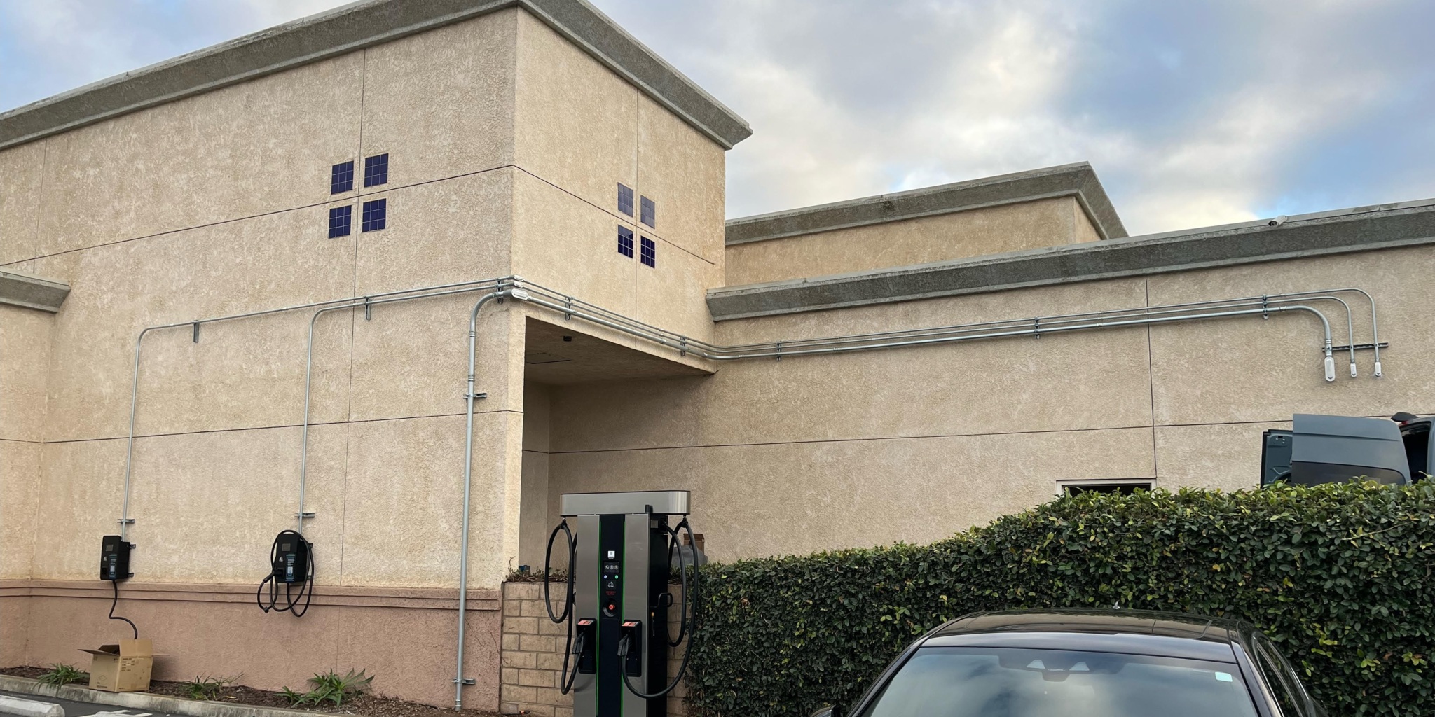
The dealership is served at 480 V, three-phase. EETS retrofitted the existing main switchboard with two new breakers. A new 125 A, three-pole breaker feeds the 480 V DC fast charger directly. A new 90 A, three-pole breaker feeds a 45 kVA, 480:120/208 V step-down transformer, which in turn feeds the new 225 A, 120/208 V distribution panel; a circuit from that panel serves the Level 2 chargers. Conduit was detailed for the site conditions – EMT above grade, PVC below grade, and PVC coated galvanized rigid transition risers and elbows – so the design reflected how the work would actually be installed.
Because the chargers represented a significant new load on a switchboard that was already in service, EETS metered the main switchboard on the line side of the main breaker for 30 days, in accordance with NEC 220.87, to establish the existing peak demand in kilowatts before any charger load was added. Sizing the additions against that measured baseline – rather than an assumed one – confirmed the existing service could absorb the new charging load.
Project Challenge
Designing into a Facility with Incomplete Documentation
There were no structural as-built drawings for the site, and the electrical record was partial. Before the design could be finalized, EETS had to pin down existing conditions that are normally read off drawings: the rating and configuration of the existing panels, the size of the breaker feeding them, the connected load on the lighting panel, the wall construction the equipment would mount to, and the weight and dimensions of the proposed transformer, panel, and chargers. Each of these had to be established through site photographs and back-and-forth verification with the contractor before the design could be committed to paper.
Adding Significant Load to an Already-Energized Service
The chargers were not a trivial addition. A DC fast charger and Level 2 charging represent substantial new demand, and they were being added to an existing main switchboard whose true spare capacity was not documented. Adding that load on the basis of an assumed existing demand risked either overloading the service or over-sizing the upgrade. The design needed a defensible, measured picture of how much of the switchboard’s capacity was actually free before any charger was connected, and a code-compliant way to protect and feed each new load once it was.
Client
Stowasser Buick GMC (through the installing electrical contractor) |
Sector
Commercial / Automotive Retail |
Location
Santa Maria, California |
Services
Electrical Engineering Design │ EV Charging Infrastructure │ Load Analysis │ NEC Code Compliance │ Structural Coordination │ Permitting Support |

Drink
As part of this expansion, AWA identified an opportunity to recover energy that was previously being wasted.
Client
Stowasser Buick GMC (through the installing electrical contractor) |
Sector
Commercial / Automotive Retail |
Location
Santa Maria, California |
Services
Electrical Engineering Design │ EV Charging Infrastructure │ Load Analysis │ NEC Code Compliance │ Structural Coordination │ Permitting Support |
Drink
As part of this expansion, AWA identified an opportunity to recover energy that was previously being wasted.
Project Overview
Stowasser Buick GMC set out to add electric-vehicle charging at its existing dealership in Santa Maria, California, a facility served by Pacific Gas & Electric (PG&E). EETS was engaged, through the installing electrical contractor, to provide the electrical engineering design that would retrofit the new charging equipment into the site’s existing 480 V service and carry the project through building-department permitting.
The retrofit added a Level 3 DC fast charger and Level 2 charging to the existing main switchboard. EETS’s scope covered the full electrical package: two new breakers in the main switchboard, a 45 kVA step-down transformer, a new 225 A, 120/208 V distribution panel, feeder and conduit design, overcurrent protection, a one-line diagram, and load calculations – all developed to the National Electrical Code (NEC).
Because the site had no structural as-built drawings and only partial electrical documentation, much of the work was field-driven: EETS established the existing conditions from site photographs, utility bills, and iterative verification with the contractor, and coordinated a structural engineering partner for the anchorage and foundation design of the wall- and floor-mounted equipment. The stamped drawing set, structural calculations, and special-inspection documentation were assembled for submittal to the building department.
Integrating New Load into an Existing Service
The dealership is served at 480 V, three-phase. EETS retrofitted the existing main switchboard with two new breakers. A new 125 A, three-pole breaker feeds the 480 V DC fast charger directly. A new 90 A, three-pole breaker feeds a 45 kVA, 480:120/208 V step-down transformer, which in turn feeds the new 225 A, 120/208 V distribution panel; a circuit from that panel serves the Level 2 chargers. Conduit was detailed for the site conditions – EMT above grade, PVC below grade, and PVC coated galvanized rigid transition risers and elbows – so the design reflected how the work would actually be installed.
Because the chargers represented a significant new load on a switchboard that was already in service, EETS metered the main switchboard on the line side of the main breaker for 30 days, in accordance with NEC 220.87, to establish the existing peak demand in kilowatts before any charger load was added. Sizing the additions against that measured baseline – rather than an assumed one – confirmed the existing service could absorb the new charging load.
Project Challenge
Designing into a Facility with Incomplete Documentation
There were no structural as-built drawings for the site, and the electrical record was partial. Before the design could be finalized, EETS had to pin down existing conditions that are normally read off drawings: the rating and configuration of the existing panels, the size of the breaker feeding them, the connected load on the lighting panel, the wall construction the equipment would mount to, and the weight and dimensions of the proposed transformer, panel, and chargers. Each of these had to be established through site photographs and back-and-forth verification with the contractor before the design could be committed to paper.
Adding Significant Load to an Already-Energized Service
The chargers were not a trivial addition. A DC fast charger and Level 2 charging represent substantial new demand, and they were being added to an existing main switchboard whose true spare capacity was not documented. Adding that load on the basis of an assumed existing demand risked either overloading the service or over-sizing the upgrade. The design needed a defensible, measured picture of how much of the switchboard’s capacity was actually free before any charger was connected, and a code-compliant way to protect and feed each new load once it was.
Engineering Solution
Power Distribution and Load Verification
EETS retrofitted the existing main switchboard with a new 125 A, three-pole breaker for the 480 V DC fast charger and a new 90 A, three-pole breaker feeding the 45 kVA transformer and the downstream 225 A, 120/208 V panel that serves the Level 2 chargers. To size these additions responsibly, EETS metered the switchboard on the line side of the main breaker for 30 days in accordance with NEC 220.87, capturing the existing peak demand in kilowatts before the charger loads were introduced. Adding the new charger load to that measured baseline – rather than a nameplate assumption – demonstrated that the existing service had the capacity to carry it, and the transformer primary breaker was sized within the limits of NEC Table 450.3(B).
Code Compliance and Equipment Coordination
Alongside the load and overcurrent analysis, EETS caught two equipment issues before they reached the field. The proposed step-down transformer was offered with aluminum windings, so EETS required that its lugs be listed for both copper and aluminum, since the project conductors are copper. Later, EETS noticed that the distribution panel as quoted had an aluminum bus rather than copper and flagged it; the panel was re-specified with a copper bus and a copper-wound transformer. EETS also recommended a unit breaker over a fused disconnect to feed the DC fast charger, as the more serviceable option for the owner, and noted that the panel as furnished carried extra single-pole breakers where a 100 A three-pole breaker was actually needed.
Structural Coordination and Permitting
Because the transformer, panel, and chargers exceeded the weight threshold for wall- and floor-mounted equipment, the building department required stamped structural design for their anchorage and foundations. EETS coordinated a structural engineering partner through that work – establishing that the mounting walls were CMU (concrete masonry) beneath the stucco finish, and gathering wall heights and mounting elevations – to produce anchorage and foundation designs for the DC fast charger, the Level 2 charger, the 45 kVA transformer, and the 225 A panel. EETS advised tying the structural design to the specific products being procured, so that a later equipment substitution would be caught rather than silently invalidating the calculations. EETS then addressed the building-department correction comments and assembled the stamped structural calculations, the signed special-inspection form, the comment responses, and the electrical drawings for submittal.
Key Technical Elements
Parameter | Detail |
Existing Service | 480 V, three-phase, served by PG&E; existing main switchboard retrofitted with two new breakers |
DC Fast Charger | Level 3 DC fast charger, 480 V; fed from a new 125 A, three-pole breaker in the main switchboard |
Transformer Feed | New 90 A, three-pole breaker feeding the 45 kVA step-down transformer |
Level 2 Charger | Served from the new 225 A, 120/208 V panel via the 45 kVA transformer |
Step-Down Transformer | 45 kVA, 480:120/208 V, copper windings; lugs listed for copper and aluminum |
Distribution Panel | 225 A, 3-phase, 4-wire, 120/208 V, copper bus, with main circuit breaker |
Load Verification | Existing peak demand measured by 30-day metering per NEC 220.87 on the line side of the main breaker, before adding charger loads |
Code Analysis | NEC 220.87 existing-load metering; NEC Table 450.3(B) transformer primary OCPD; NEC 240.21 tap rules evaluated |
Conduit | EMT above grade; PVC below grade; transition risers and elbows PVC coated galvanized rigid |
Structural Scope | Anchorage and foundation design for chargers, transformer, and panel on CMU construction; special-inspection form |
Deliverables | Stamped electrical drawings, one-line and load calculations, stamped structural calculations, comment responses, special-inspection form |
Project Outcome
The dealership received a complete, code-compliant retrofit design: a 480 V DC fast charger and Level 2 charging added to the existing main switchboard through two new breakers, a 45 kVA transformer, and a new 225 A, 120/208 V panel. The addition was justified against measured demand – EETS metered the switchboard for 30 days under NEC 220.87 to confirm the existing service could carry the new load. Equipment specifications – copper bus and copper windings – and the anchorage of every wall- and floor-mounted unit were verified before installation. EETS resolved the building-department corrections and assembled the full permit package – electrical drawings, one-line and load calculations, stamped structural calculations, comment responses, and the special-inspection form – for submittal, so the contractor could move to installation on an approved set.
Value Delivered by EETS
EETS turned an existing, in-service facility with thin documentation into a measured, permittable, code-compliant EV charging retrofit.
Turning Incomplete Site Information into a Permittable Design
With no structural as-builts and only partial electrical records, EETS reconstructed the existing conditions the design depended on – panel ratings, breaker sizes, connected loads, wall construction, and equipment weights – from site photographs, utility bills, and methodical verification with the contractor. Where the record could not confirm an existing load, EETS applied the NEC 220.87 metering path rather than guessing. That groundwork is what let a design proceed on a site that, on paper, was not fully documented.
Catching Problems Before They Reached the Field
Several issues were caught at the desk instead of on site: a transformer offered with aluminum windings, a distribution panel quoted with an aluminum bus instead of copper, and a service addition that could have been sized on assumption rather than measurement. Each catch – re-specifying to copper, metering the switchboard to prove the spare capacity, and sizing the transformer breaker within the code limit – avoided a change order, a failed inspection, or a call-back during installation.
One Coordinator Across Electrical, Structural, and Permitting
EETS carried the project across three fronts that could easily have fragmented: the electrical design, the structural anchorage handled through a structural partner, and the building-department permitting. Managing the structural scope, advising that the design be tied to the specific equipment procured, responding to the correction comments, and pulling the stamped calculations and special-inspection form together into one submittal gave the contractor a single point of accountability from design through approval.
Drink
As part of this expansion, AWA identified an opportunity to recover energy that was previously being wasted.