
Reconfiguration Study for a Historic Downtown Substation
Sacramento Municipal Utility District (SMUD) | Station ‘A’ 115 kV / 12 kV Reconfiguration Study | Downtown Sacramento, California
Project Overview
Station ‘A’, built in 1894 and a Registered California Historic Landmark, is one of two 115 kV–12 kV substations serving SMUD’s downtown Sacramento network distribution system. After more than a century in service the station carried two significant reliability gaps: two of its three incoming 115 kV lines had no local protection, and its 12 kV switchgear was aged – some assemblies over 50 years old – and increasingly unreliable. Compounding both, the site is extremely tight, the building is a protected landmark, and the downtown network it feeds cannot be taken out of service.
SMUD engaged EETS to study how to add the missing protection, replace the switchgear, and reconfigure the station for improved reliability and control – all while minimizing downtime and maintaining continuity of service. EETS developed and evaluated a broad field of 115 kV and 12 kV reconfiguration alternatives, each with one-line diagrams, plans and elevations, a cost estimate, and a construction sequence, then screened them to a viable set and made recommendations.
The study’s deliverable was not a single answer but a decision-ready menu: options spanning the full cost-and-reliability spectrum, every one of them shaped to fit a historic, space-constrained site and to be built without ever shutting an entire network down.
The Station and Its Constraints
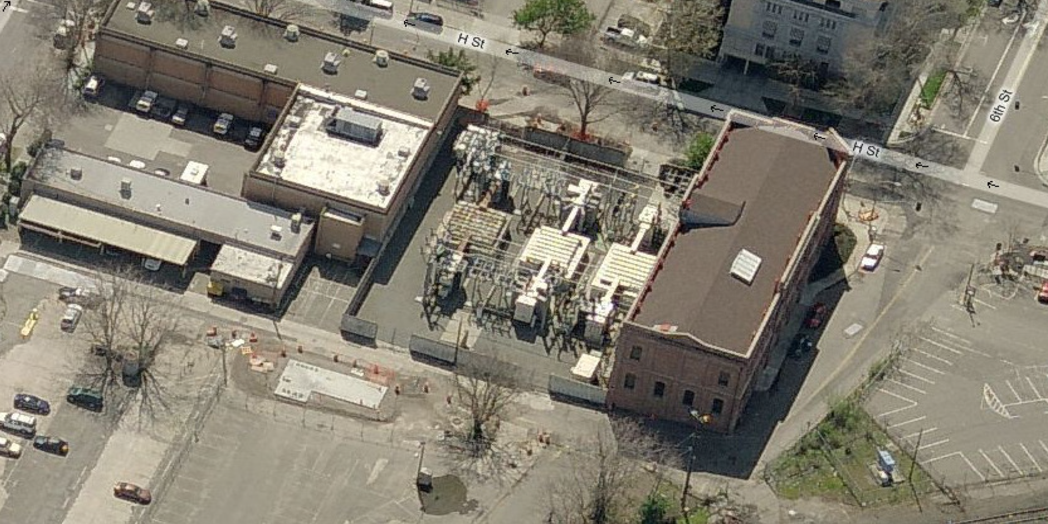
Station ‘A’ occupies a single downtown block, with a historic building of roughly 55 by 160 feet beside a substation yard of only about 115 by 160 feet. Three 115 kV underground lines feed it: two low-pressure, oil-filled pipe cables installed in 1953 from the North City Substation, which terminate directly to the north and south overhead buses with no breakers or disconnects at Station ‘A’, and a third, solid-dielectric line from Station ‘D’ that terminates to existing gas-insulated switchgear. Six 115:12 kV transformers – two rated 23.2 MVA, two 20 MVA, and two 25 MVA – serve three networks, each transformer sized to pick up its network’s entire load, feeding three aged 12 kV metal-clad switchgear lineups and eighteen outgoing underground feeders.
The physical constraints drive the engineering. There is no room to install fire walls between the transformers, so protection has to compensate; there is little room to add 115 kV equipment without building upward; and because the downtown network depends on this station, any reconfiguration has to be staged so that no single network is ever fully de-energized during construction.
Project Challenge
Modernizing a Space-Constrained Landmark That Cannot Go Dark
The station needed real change – protection on the two unprotected incoming lines, replacement of failing switchgear, and ideally primary protection on the transformers – but every square foot of a landmark site and its small yard was already spoken for, and the downtown network could not be interrupted. The problem was not just choosing better equipment; it was fitting that equipment onto the site at all, and sequencing its installation so the three networks stayed in service throughout construction.
A Wide Field of Options with Steep Trade-offs
The ways to reconfigure the 115 kV yard ranged enormously – from simply adding protection to the incoming feeders, to completing a partial (quasi-) ring bus, to a full ring bus built either conventionally or with gas-insulated switchgear, to demolishing the yard and rebuilding it around three new transformers. The options traded off against one another on cost, reliability, equipment height and footprint, whether underground cables or transformers had to be relocated, and how much of the network had to be taken down to build them. The challenge was to evaluate them all on a consistent basis and determine which actually fit the site.
Client
Sacramento Municipal Utility District (SMUD)
Sector
Public / Municipal Electric Utility
Location
Downtown Sacramento, California
Services
Substation Reconfiguration Study │ Alternatives Analysis │ 115 kV and 12 kV System Planning │ Protection and Reliability │ Cost Estimating and Construction Sequencing

Drink
As part of this expansion, AWA identified an opportunity to recover energy that was previously being wasted.
Client
Sacramento Municipal Utility District (SMUD)
Sector
Public / Municipal Electric Utility
Location
Downtown Sacramento, California
Services
Substation Reconfiguration Study │ Alternatives Analysis │ 115 kV and 12 kV System Planning │ Protection and Reliability │ Cost Estimating and Construction Sequencing
Drink
As part of this expansion, AWA identified an opportunity to recover energy that was previously being wasted.
Project Overview
Station ‘A’, built in 1894 and a Registered California Historic Landmark, is one of two 115 kV–12 kV substations serving SMUD’s downtown Sacramento network distribution system. After more than a century in service the station carried two significant reliability gaps: two of its three incoming 115 kV lines had no local protection, and its 12 kV switchgear was aged – some assemblies over 50 years old – and increasingly unreliable. Compounding both, the site is extremely tight, the building is a protected landmark, and the downtown network it feeds cannot be taken out of service.
SMUD engaged EETS to study how to add the missing protection, replace the switchgear, and reconfigure the station for improved reliability and control – all while minimizing downtime and maintaining continuity of service. EETS developed and evaluated a broad field of 115 kV and 12 kV reconfiguration alternatives, each with one-line diagrams, plans and elevations, a cost estimate, and a construction sequence, then screened them to a viable set and made recommendations.
The study’s deliverable was not a single answer but a decision-ready menu: options spanning the full cost-and-reliability spectrum, every one of them shaped to fit a historic, space-constrained site and to be built without ever shutting an entire network down.
The Station and Its Constraints
Station ‘A’ occupies a single downtown block, with a historic building of roughly 55 by 160 feet beside a substation yard of only about 115 by 160 feet. Three 115 kV underground lines feed it: two low-pressure, oil-filled pipe cables installed in 1953 from the North City Substation, which terminate directly to the north and south overhead buses with no breakers or disconnects at Station ‘A’, and a third, solid-dielectric line from Station ‘D’ that terminates to existing gas-insulated switchgear. Six 115:12 kV transformers – two rated 23.2 MVA, two 20 MVA, and two 25 MVA – serve three networks, each transformer sized to pick up its network’s entire load, feeding three aged 12 kV metal-clad switchgear lineups and eighteen outgoing underground feeders.
The physical constraints drive the engineering. There is no room to install fire walls between the transformers, so protection has to compensate; there is little room to add 115 kV equipment without building upward; and because the downtown network depends on this station, any reconfiguration has to be staged so that no single network is ever fully de-energized during construction.
Project Challenge
Modernizing a Space-Constrained Landmark That Cannot Go Dark
The station needed real change – protection on the two unprotected incoming lines, replacement of failing switchgear, and ideally primary protection on the transformers – but every square foot of a landmark site and its small yard was already spoken for, and the downtown network could not be interrupted. The problem was not just choosing better equipment; it was fitting that equipment onto the site at all, and sequencing its installation so the three networks stayed in service throughout construction.
A Wide Field of Options with Steep Trade-offs
The ways to reconfigure the 115 kV yard ranged enormously – from simply adding protection to the incoming feeders, to completing a partial (quasi-) ring bus, to a full ring bus built either conventionally or with gas-insulated switchgear, to demolishing the yard and rebuilding it around three new transformers. The options traded off against one another on cost, reliability, equipment height and footprint, whether underground cables or transformers had to be relocated, and how much of the network had to be taken down to build them. The challenge was to evaluate them all on a consistent basis and determine which actually fit the site.
Engineering Solution
Evaluating the Full Field of Alternatives
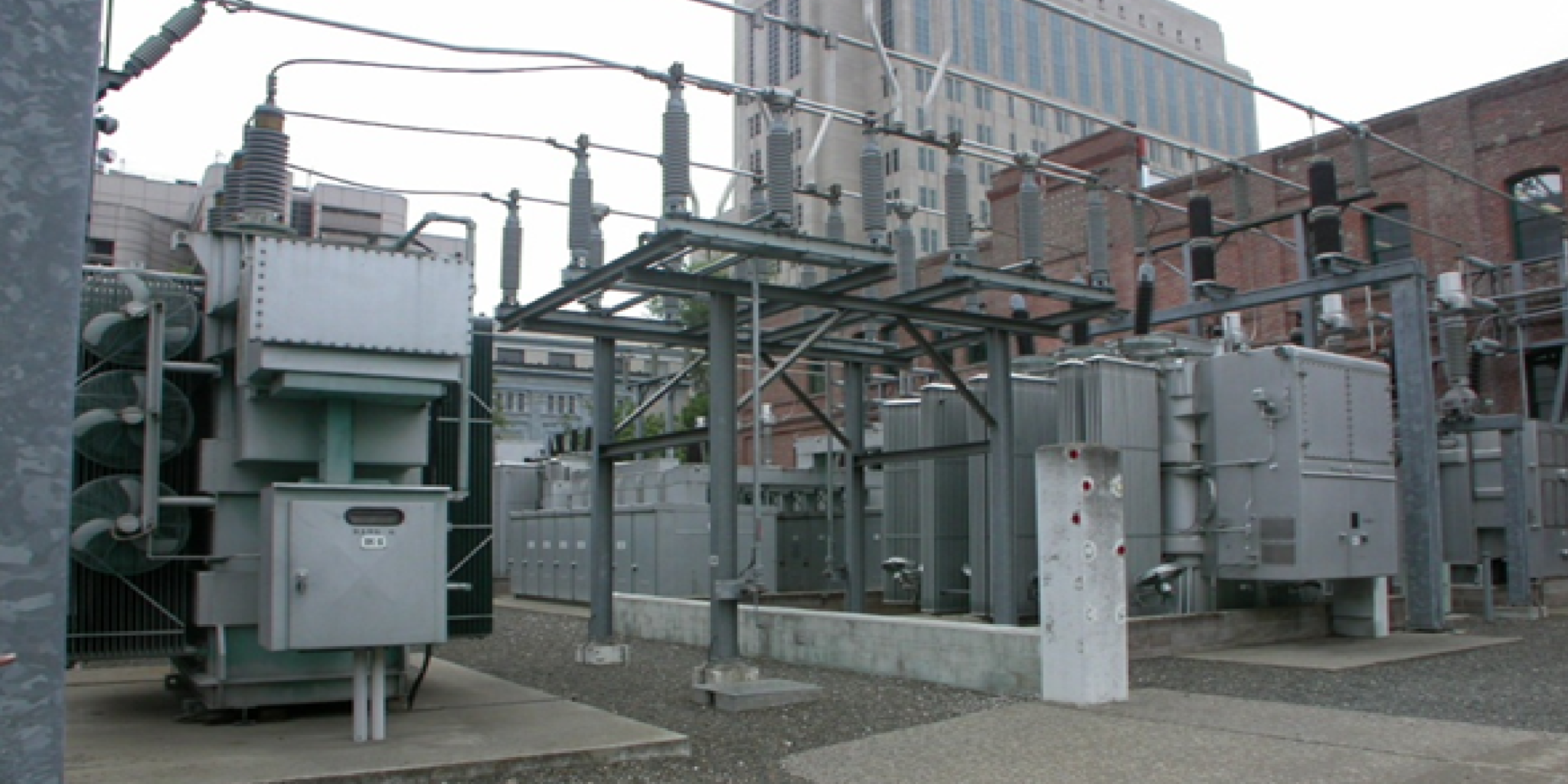
EETS developed and evaluated roughly sixteen 115 kV alternatives, organized into five families: adding protection to the two North City feeders; adding that protection plus primary protection on all six transformer high sides; reconfiguring as a five-position quasi-ring bus using the existing transformers; reconfiguring as a nine-position ring bus; and demolishing the yard to rebuild as a six-position ring with three new transformers. In parallel, EETS evaluated ten 12 kV switchgear alternatives – outdoor and indoor, in vacuum and SF6 gas-insulated technologies, across single- and double-bus and single- and double-breaker arrangements. Each alternative was documented with a one-line diagram, plan and elevation drawings, an advantages-and-disadvantages evaluation, a cost estimate, and a staged construction sequence.
The Finding That Unlocked the Best Options
Early in the study it appeared that fitting a ring bus onto the site would require relocating one or more of the North City or Station ‘D’ underground cables – an expensive, disruptive proposition. On closer investigation, EETS determined that, by using elevated structures and overhead bus, there was in fact enough room to build a true ring bus, or to complete the existing quasi-ring, within the existing footprint. That finding was pivotal: it let EETS discard the most disruptive and costly paths – the gas-insulated rings, and the full demolition-and-rebuild – in favor of circuit-switcher arrangements that reuse the existing transformers and underground cables.
Screening to Viable Options and Recommending
EETS discarded every alternative that required moving an underground cable, replacing the transformers, or leaving the ring incomplete, along with the indoor 12 kV options whose building penetrations drove up cost – narrowing the field to eight viable 115 kV alternatives and one 12 kV alternative. For the 12 kV system, EETS recommended Alternative ‘E’, an outdoor double-bus, double-breaker vacuum switchgear lineup that is both extremely compact and the highest-reliability option. For the 115 kV yard, EETS recommended two schemes bracketing the reliability spectrum: a nine-position ring bus built with circuit switchers for the highest operational reliability, or, as a least-cost upgrade, adding circuit switchers to protect the two North City feeders. Every recommended 115 kV configuration can be constructed in stages without a full shutdown of any of the three networks.
Key Technical Elements
Parameter | Detail |
Station | Station ‘A’ – built 1894, California Historic Landmark; one of two 115/12 kV substations on SMUD’s downtown Sacramento network |
Incoming 115 kV | Three underground lines: two unprotected 1953 oil-filled pipe cables from North City, and one solid-dielectric line from Station ‘D’ terminating to existing GIS |
Transformers | Six 115:12 kV units – two 23.2 MVA, two 20 MVA, two 25 MVA – one per side of three networks, each sized for its network’s full load |
12 kV Switchgear | Three aged metal-clad double-bus lineups (some over 50 years old); eighteen outgoing underground feeders |
Site Constraint | ≈ 115 ft × 160 ft yard; no room for inter-transformer fire walls |
115 kV Alternatives | ≈ 16 across five families: feeder protection; + transformer high-side protection; five-position quasi-ring; nine-position ring; demo and rebuild with three new transformers |
12 kV Alternatives | 10 options: outdoor (A–G) and indoor (H–J); vacuum and SF6 gas-insulated; single/double bus and single/double breaker |
|
|
Key Finding | A ring bus fits within the existing footprint using elevated structures and overhead bus – no underground-cable relocation required |
Recommended 12 kV | Alternative ‘E’- outdoor double-bus, double-breaker vacuum switchgear |
Recommended 115 kV | Nine-position circuit-switcher ring for highest reliability, or circuit switchers on both North City feeders as least-cost protection |
Continuity Requirement | All recommended configurations buildable in stages, with no full shutdown of any of the three networks |
Project Outcome
EETS delivered SMUD a comprehensive reconfiguration study for Station ‘A’: dozens of 115 kV and 12 kV alternatives developed, drawn, costed, and compared, then screened to a viable set. The study established that the station’s core reliability gaps – unprotected incoming lines and aged switchgear – could be closed without relocating underground cables, replacing transformers, or shutting down the downtown network. For the 12 kV system it recommended compact, high-reliability outdoor double-breaker vacuum switchgear; for the 115 kV yard it offered a nine-position circuit-switcher ring for the highest reliability or circuit-switcher protection on the two North City feeders as a least-cost upgrade – each staged to keep all three networks in service. SMUD came away with a decision-ready set of options across the cost-and-reliability spectrum, every one fitted to the historic, space-constrained site.
Value Delivered by EETS
EETS turned a constrained, high-stakes site into a set of buildable, fully-costed options, and found the insight that made the best of them possible.
Buildable Options for an Unforgiving Site
Working within a 110-year-old landmark, a yard barely larger than a building lot, two unprotected incoming lines, and a network that cannot go dark, EETS did not simply name a fix. It developed a full field of alternatives, each drawn to plan and elevation, costed, and given a construction sequence, so SMUD could see exactly what would fit, what it would cost, and how it would be built while the station kept running. Turning hard constraints into a concrete menu of choices is the value a reconfiguration study exists to deliver.
An Insight That Unlocked Cheaper, Better Options
The pivotal contribution was recognizing that a ring bus could fit within the existing footprint using elevated structures and overhead bus, without relocating the underground cables. That single finding removed the most expensive and disruptive options from contention – gas-insulated rings and a full demolition-and-rebuild – and pointed instead to circuit-switcher arrangements that reuse the existing transformers and cables to deliver higher reliability at a fraction of the cost.
Reliability and Continuity Built Into Every Recommendation
Every recommended configuration closes the station’s protection gaps – adding control of the incoming lines and, in the ring options, each transformer, which also compensates for the fire walls the site has no room to build – and every one can be constructed in stages without fully de-energizing any of the three downtown networks. By holding reliability and continuity of service as fixed requirements rather than trade-offs, EETS ensured that whichever option SMUD selected, it would extend the useful life of a landmark station without putting downtown’s power at risk.
Drink
As part of this expansion, AWA identified an opportunity to recover energy that was previously being wasted.